
UPS R12000 XR Models Maintenance and Service Guide
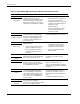
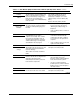
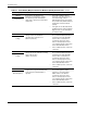

Table Of Contents
- HP UPS R12000 XR Models Maintenance and Service Guide
- Notice
- Contents
- About This Guide
- Chapter 1: Safety and Product Information
- Chapter 2: Illustrated Spare Parts List
- Chapter 3: Identifying Components
- Front Components
- Modes of Operation
- Rear Components
- Matching the Utility Voltage
- Module Locations
- Configuring the UPS Using the LCD Menu
- Chapter 4: Removal and Replacement Procedures
- Chapter 5: Troubleshooting
- Chapter 6: Specifications
- Index

Troubleshooting
HP UPS R12000 XR Models Maintenance and Service Guide 5-3
Table 5-1: Main Module (MM) and Electronics Modules (M1-M4) Active Alarms continued
LCD Display Possible Cause Actions to Take
x Alarms
Battery n Test
Failed
The UPS detects a manual battery test
failure. A manual battery test failure is
reported when battery voltage is less
than 1.8 volts per cell during the
first 75 seconds of unscheduled Battery
mode operation.
The variable n indicates the slot in
which the faulty battery module is
installed. (For example, slot 1 is the
uppermost bay of the four battery bay
slots.)
Replace the faulty battery module.
x Alarms
Bypass Not
Available
Bypass mode is currently unavailable
due to the voltage or frequency being
outside the valid operating range for
the UPS.
• To verify that the voltage settings
are correct, refer to the section,
“Matching the Utility Voltage,” in
Chapter 3.
• If the condition persists, contact an
electrician.
x Alarms
Calibration Failed
The UPS triggers this alarm when the
autocalibration process fails to
complete successfully. This could be
the result of an interruption from an
operating mode transition or because
of UPS load changes occurring while
autocalibration was in progress.
• The autocalibration process
reschedules and automatically
restarts when the UPS conditions
are conducive for the operation to
complete.
• If the condition persists, locate and
replace the faulty module.
x Alarms
DC Link Over
Voltage
At least one electronics module detects
abnormally high rail voltage levels and
shuts down to protect itself and the
load from damage.
This could be caused by a hardware
failure.
Switch to Manual Bypass mode. Locate
and replace the faulty module.
x Alarms
Fan Failure
At least one electronics module detects
that one or both of its cooling fans has
failed. The detecting module
immediately shuts down to protect its
heat-sensitive components.
• Check the fans for blockage. If a
fan is blocked, remove the
blockage, switch to Manual Bypass
mode, and restart the system.
• If a fan is not blocked and the
problem persists, switch to Manual
Bypass mode. Locate and replace
the faulty module.
x Alarms
Fuse Failure
The UPS detects that one or more of
the internal module fuses have failed.
Switch to Manual Bypass mode. Locate
and replace the faulty module.
continued