
Managing Superdome Complexes: A Guide for HP-UX System Administrators


Planning Superdome Configurations
Building Blocks and Definitions
Appendix A 317
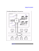
What is an I/O Chassis?
Terms:
• CPU cabinet: see “What is a CPU Cabinet?” on page 299.
• Cell: see “What is a Cell?” on page 303.
• Partition: see “What is a Partition?” on page 298.
• GSP (Guardian Service Processor): see “What is the Guardian
Service Processor?” on page 296.
Full Glossary on page 287 .
An I/O chassis enables a cell, and hence a partition to communicate
with I/O devices such as the system console, disk drives and the network.
It contains slots for I/O cards and is sometimes referred to as a
cardcage.
At first release, each CPU cabinet holds a maximum of four I/O chassis,
two in each of the cabinet's two I/O bays (front and rear). I/O bays are
the apertures in the CPU cabinet that the I/O chassis fit into. Partition
Manager and other utilities report the location of an IO chassis in the
form:
cabinet_#, bay_#, chassis_#
At first release, only 12-slot chassis are available.
See “Partitions, Cells and I/O Chassis” on page 333 for more
information.
I/O Cards
At first release, each I/O chassis contains 12 PCI (Peripheral Card
Interface) slots, numbered 0-11, right to left when looking at the chassis
from the front.
• Slots 0, 1, 2, 3, 8, 9, 10, and 11 are 2X (33MHZ) 5-volt-only slots.
• Slots 4, 5, 6, and 7 are 4X (66MHZ) 3.3-volt-only slots.
• Universal PCI cards (cards that support both 5 and 3.3 volts) can
plug into any slot, but keep in mind that:
❏ Universal 2X PCI cards plugged into 4X slots will run only at 2X
speed (33MHZ).
❏ Universal 4X PCI cards plugged into 2X slots will also run only at
2X speed.