
ACC HDLC-NRM (SDLC) User's Guide


Chapter 3 41
Using HDLC-NRM (SDLC) Protocols
Status and Error Messages
Command/Response Reject Reason Codes
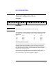
The format o f the command/response reject reason information is given
below. This data is passed to the application in the data portion of the
indicated unsolicited status messages, as described under the Error
Recovery section. This informat ion is summarized f rom ISO 4 335
standard, section 7.3.3.2. Please refer to the standard for a more detailed
description.
Of pri mary interest here are the four one bit flags named w, x, y and z.
The meanings are as follows:
w when set to “1” indicates that the rejected control field
was undefined or not implemented.
x when set to “1” indicates that the rejected frame
contains an I-field when it is illegal for this type of
frame. w is also set to “1” in this case.
y when set to “1”indicates that the rejected frame was too
long.
z when set to “1” indicates that the rejected control field
contains an invalid receive sequence number N(R).
NOTE ISO 4335 Section7.3.3.2describes the format of thisinformation field for
a Frame Reject response in modulo 8 using bit numbers from 1 (for the
first transmitted bit) to 20. This I-field is padded with 4 extra bits to
make 3 whole octets, as a llowed in the standard. The a bove diagram uses
the more usual convention of showing the most significant bit of each
byte on the left, and the least significant bit of each byte on the right.
When data is transmitted over the wire, the least significant bit is
transmitted first beginning at byte 1.
Byte 1 Byte 2 Byte 3
Rej. frame control field N(r) C/R N(s) 0 z y x w