
ACC Installation and Configuration Guide


Chapter 2 45
Software Installation and Verification
Installation Verification
Cabling and Clock Source Requirements
When testing a single port looped back on itself, you connect a
terminated connector or loopback hood to one of the ports on either the
multiplexer panel or the (2-Channel) output cable. This serves to connect
the Receive Clock (RC) to the External Timing Clock (ETC), or CCITT
circuit 115 to CCITT circuit 113. Refer to the hardware reference manual
for more details.
NOTE A Loopback hood and cable is supplied with the Interchange Panel or
Cable accessory.
For this type of loopb ack test, the Internal clock mode is required. (See
the ACC Utilities Reference Guide for a description of valid ACC clock
modes.) Referring to the sample configuration files in Appendix A ,
“Files, Utilities, and Daemons ,” on page 75 of this manual, note that the
Port-Definition statements, which are automatically generated during
installation, define clock mode for even-numbered ports as “Int”, and for
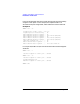
odd-numbered ports as “Ext” or external clock mode as follows:
8-Channel & 2-Channel
Port-Definition
Port 0:0 RS232 57600 Int SDLC x1 NRZ
Port 0:1 RS232 57600 Ext SDLC x1 NRZ
Port 0:2 RS232 57600 Int SDLC x1 NRZ
Port 0:3 RS232 57600 Ext SDLC x1 NRZ
Port 0:4 RS232 57600 Int SDLC x1 NRZ
Port 0:5 RS232 57600 Ext SDLC x1 NRZ
Port 0:6 RS232 57600 Int SDLC x1 NRZ
Port 0:7 RS232 57600 Ext SDLC x1 NRZ
Port 1:0 RS232 57600 Int SDLC x1 NRZ
Port 1:1 RS232 57600 Ext SDLC x1 NRZ
NOTE If you are using an 8-port PCI card with an external loopback cable, you
need to specif y the clocking parameter “ExIn” for an external DTE
configured port.