
ACC X.25 Protocol User's Guide


Chapter 3 59
ZX25D X.25 Protocol Driver
Implementation Notes
acknowledgment. When an I-frame is received, timer T2 is started, and if
an I-frame is transmitted, the acknowledgment will be sent with it and
timer T2 w ill be cancelle d. Only if T2 expires (no I-frame having been
transmitted) will an explicit flow control frame be transmitted. The T2
timer value may be explicitly set by using the T2_timer statement. If this
statement has not been defined in the Link Term entry, T2 is set to half
of the value of T1, and for a 9600 baud link, T1 will usually be set to 400
milliseconds. N2 is usually set to 10.
Timer T4 is used at Level 2 (LAP-B) for DTEs. This is the maximum time
the DTE will allow without frames being exchanged on the data link. The
value of T4 is approximately 6*N2*T1. Note that for a DCE, this timer is
called T3.
Packet level timers are implemented according to the ITU-T/ISO
recommendation for T10, T11, T12, T13, T20, T21, T22, T23, T25, and
T26. A 180-second timeout is applied to the receipt of data packet
acknowledgments. At the end of the time-out, the virtual circuit will be
reset.
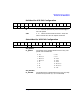
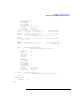
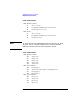
Summary of T imer Values
The following sections shows the mandatory and optional X.25 timer
values. Note that the DCE timer values are shown for completeness only.
NOTE The X .25 Protocol product supports s ome of the features of a DCE
interface, however these are i ntended to be used for loopback
configurations and direct computer to computer connections where the
other end of the connection is a DTE device.