
Installing and Administering HP EISA FDDI/9000 and HP HSC FDDI/9000


48 Chapter 3
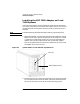
Installing the HP HSC FDDI/9000 Adapter
Connecting the Adapter to the Network
Connecting the Adapter to the Network
Keep the dust cap(s) on the ends of the cable and on the transceivers of
the adapter until the connections are ready to be made. This prevents
dirt and oils from soiling any important surfaces. Do not attempt to
polish the connectors with a cloth made of synthetic fibers; this charges
the fiber and attracts dust.
When connecting a fiber optic cable, do not stretch, puncture, or crush
the cable with staples or heavy equipment. Always maintain the
minimum bend radii specified by the cable manufacturer. The fiber in
fiber optic cable can suffer damage if the cable is bent in small radii. The
minimum bend radius is usually 10-20 times a cable’s outer diameter.
CAUTION Do not force the connectors when attaching the cable — they are keyed
connections and fit one way only.
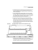
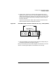
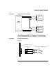
There are two ways to connect the adapter to the FDDI network. It can
be connected directly to the adjacent stations in a dual-ring network or to
a concentrator (DAC or SAC), typically dual-homed for additional fault
tolerance. You can use either SC-to-SC duplex cables or SC
duplex-to-MIC adapter cables with MIC-to-MIC cables.
You can use an Optical Bypass Switch (OBS) between the adapter and
the dual ring. An OBS maintains continuity of the primary and
secondary ring when the station is powered down, or in the event of an
adapter failure.
Signals must be routed such that the primary Tx output from each
station is routed to the primary Rx input of its neighbors, and the
secondary Tx output is routed to the secondary Rx input of the other
neighbor, and so forth, as shown in Figure 3-5.