
Installing and Administering PPP


146 Appendix A
Modem Connections
RS-232 Interface
The RS-232 standard utilizes nine pins for signaling, although many
serial interfaces provide 25. The other 16 pins can be used for testing or
secondary signaling. Smaller 9-pin connectors support standard signals
and save space.
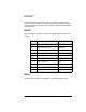
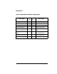
DB-25
25 pin connectors, or DB-25, use pins 2 though 8 and pins 20 and 22 as
shown:
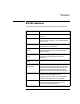
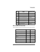
DB-9
Standard 9 pin connectors, called DB-9, use the following pin setup:
Pin Signal Signal Direction
1 Protective Ground both
2 Transmit Data (TD) from DTE
3 Receive Data (RD) from DCE
4 Request To Send (RTS) from DTE
5 Clear To Send (CTS) from DCE
6 Data Set Ready (DSR) from DCE
7 Signal Ground both
8 Carrier Detect (CD) from DCE
20 Data Terminal Ready (DTR) from DTE
22 Ring Indicator (RI) from DCE