A9782A & A9784A PCI-X 2 Gigabit Fibre Channel and Gigabit Ethernet Combination Card Installation Guide HP-UX & OpenVMS Networking Manufacturing Part Number: 5971-4264 E0305 Printed in the US © Copyright 2004-2005 Hewlett-Packard Development Company, L.P.
Legal Notices The information in this document is subject to change without notice. Hewlett-Packard makes no warranty of any kind with regard to this manual, including, but not limited to, the implied warranties of merchantability and fitness for a particular purpose. Hewlett-Packard shall not be held liable for errors contained herein or direct, indirect, special, incidental or consequential damages in connection with the furnishing, performance, or use of this material.
Contents 1. HP-UX Installation Step 1: Access the system card bay . . . . . . . . . . . . . . . . . . . . . . . . . . . . . . . . . . . . . . . . . . . . . . . . . . . . . . . 8 Step 2: Install the card . . . . . . . . . . . . . . . . . . . . . . . . . . . . . . . . . . . . . . . . . . . . . . . . . . . . . . . . . . . . . . . . 8 Step 3: Connect the card to the network. . . . . . . . . . . . . . . . . . . . . . . . . . . . . . . . . . . . . . . . . . . . . . . . . . .
Contents 4
1 HP-UX Installation These instructions apply to A9782A and A9784A PCI-X combination cards on HP-UX 11i v1 and 11i v2. The following installation steps are detailed in this section: • “Step 1: Access the system card bay” • “Step 2: Install the card” • “Step 3: Connect the card to the network” • “Step 4: Connect the fibre channel devices” • “Step 5: Prepare to install the software” • “Step 6: Install the latest software.
HP-UX Installation HP welcomes your input. Please email us at: netinfo_feedback@cup.hp.com with comments or suggestions on HP I/O Cards or related documentation.
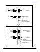
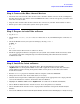
HP-UX Installation A9784A PCI-X Combination Card with Copper-based Gigabit Ethernet Fibre Channel Connector (Duplex LC) FIBRE CHANNEL 1Gb 2Gb 1000B-T 1000 100 10 LNK/ACT 1000Base-T Connector (RJ-45) PCI-X 133 MHz Link/Activity LED On solid = link established Blinking = Data transmitted or received A9782A PCI-X Combination Card with Fiber-based Gigabit Ethernet Fibre Channel Connector (Duplex LC) FIBRE CHANNEL 1Gb 2Gb 1000Base-SX Connector (Duplex LC) 1000B-SX ACT LINK PCI-X 133 MHz Chapter 1 Activ
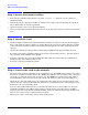
HP-UX Installation Step 1: Access the system card bay Step 1: Access the system card bay • If the system is running, shut it down by executing: shutdown -h. Respond “y” to the continue to shutdown prompt. • Wait for the system to shut down completely, and then power off the system by pressing the system off button. Ensure that the system is grounded. • Open the system to gain access to the PCI backplane. • Select an empty PCI or PCI-X slot and remove the slot cover.
HP-UX Installation Step 4: Connect the fibre channel devices Step 4: Connect the fibre channel devices • Attach the LC connector from a fibre channel cable to the fibre channel connector on the card (Figure 1). For fibre channel, the cable must be 50 micron MMF. If the remote connection is type SC, you will need an LC-to-SC conversion cable. • Plug the other end of the fibre channel cable into the connector on your fibre channel switch or device. • Ensure power cable is connected to system.
HP-UX Installation Step 7: Configure the card using SAM • Activate the YES button at the Confirmation Window to confirm that you want to install the software. swinstall loads the fileset, runs the control scripts for the filesets, and builds the kernel. This should take about 3 to 5 minutes. When the status field indicates Ready, click Done. A Note Window then opens. Click the OK button to reboot the system.
HP-UX Installation Step 9: Verify the LAN installation output lists all mass storage devices attached to the card. If the correct driver is installed, but the card does not show in the ioscan output, the driver is not recognizing the card. Make sure the card is seated and connectors are attached tightly, then if the problem persists, contact HP for assistance.
HP-UX Installation Optional Step: Configure Jumbo Frames Size Optional Step: Configure Jumbo Frames Size NOTE • (Jumbo frames are supported only at 1000 Mbit/s Jumbo frames for the igelan driver on HP-UX 11i v1 or 11i v2 have an mtu_size of 9000 bytes. If you are using Jumbo Ethernet frames, ensure that all end stations on a given LAN* have the same maximum transmission unit (MTU) setting. However, switch ports in your LAN can have any MTU setting greater than or equal to the end station’s MTU.
HP-UX Installation Network Card Configuration Worksheet Network Card Configuration Worksheet Fill out one worksheet for each network card you are installing. Table 1-1 Ethernet Card Configuration Worksheet How to Configure (see Note 1) Required / Optional Default Internet Address Required 0.0.0.0 SAM or ifconfig or edit /etc/rc.config. d/netconf 196.6.20.2 Subnet mask Required if using subnetting Subnet mask not used SAM or ifconfig or edit /etc/rc.config. d/hpigelanconf 255.255.248.
HP-UX Installation Network Card Configuration Worksheet NOTE Note 1: To configure values permanently, edit the configuration files using SAM or an editor such as “vi”. Using lanadmin will not preserve your settings across reboots. NOTE Note 2: The speed configuration of the card can be 10, 100, or 1000Mbps and is determined by the speed setting of the hub or switch port to which the card is connected. The card automatically senses this speed. The Base-T card only runs at one speed at a time.
2 OpenVMS Installation These instructions apply to A9782A and A9784A PCI-X combination cards on OpenVMS and contains the following sections: • “Step 1: Verify Driver Software” • “Step 2: Access the system card bay” • “Step 3: Install the card” • “Step 4: Connect the card to the network” • “Step 5: Connect the fibre channel devices” • “Step 6: Boot the System” • “Step 7: Configure the card using LANCP” • “Network Card Configuration Worksheet” • “Step 8: Verify Installation” • “Optional Ste
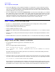
OpenVMS Installation A9784A PCI-X Combination Card with Copper-based Gigabit Ethernet Fibre Channel Connector (Duplex LC) FIBRE CHANNEL 1Gb 2Gb 1000B-T 1000 100 10 LNK/ACT 1000Base-T Connector (RJ-45) PCI-X 133 MHz Link/Activity LED On solid = link established Blinking = Data transmitted or received A9782A PCI-X Combination Card with Fiber-based Gigabit Ethernet Fibre Channel Connector (Duplex LC) FIBRE CHANNEL 1Gb 2Gb 1000Base-SX Connector (Duplex LC) 1000B-SX ACT LINK PCI-X 133 MHz 16 Activity L
OpenVMS Installation Step 1: Verify Driver Software Step 1: Verify Driver Software The drivers for the Gigabit Ethernet and Fibre Channel software are included in the OpenVMS installation. To check for the latest software patches, search for OpenVMS under http://www.itrc.hp.com. Step 2: Access the system card bay • If the system is running, shut it down by executing: MCR SYSMAN SHUTDOWN NODE. • Wait for the system to shut down completely, and then power off the system by pressing the system off button.
OpenVMS Installation Step 5: Connect the fibre channel devices Step 5: Connect the fibre channel devices • Attach the LC connector from a fibre channel cable to the fibre channel connector on the card (Figure 1). For fibre channel, the cable must be 50 micron MMF. If the remote connection is type SC, you will need an LC-to-SC conversion cable. • Plug the other end of the fibre channel cable into the connector on your fibre channel switch or device. • Ensure power cable is connected to the system.
OpenVMS Installation Network Card Configuration Worksheet Network Card Configuration Worksheet Table 2-1 Network Card Configuration Worksheet Data Type Required / Optional Default Where to Configure Example Station address Built-in and cannot be changed As shown on card not configurable 0x0060b0c4012f Link configuration Optional Autonegotiating LANCP MC LANCP SET DEVICE /AUTONEGOTIA TE Link speed/duplex mode Optional Autonegotiating Hub or switcha or LANCP MC LANCP SET DEVICE/ SPEED=10
OpenVMS Installation Step 8: Verify Installation Reference count 0 Default buffer size 0 Current preferred CPU Id 3 Fastpath 1 Current Interrupt CPU Id 3 FC Port Name 5006-0B00-001C-E68C FC Node Name 5006-0B00-001C-E68D 4. Run the LANCP SHOW CONFIGURATION command to verify that a LAN device was installed. In the following example, the device EWCO is the A9782A device.
OpenVMS Installation Optional Step: Jumbo Frames Size Optional Step: Jumbo Frames Size NOTE Jumbo Frames Size (Jumbo frames are supported only at 1000 Mbit/s Jumbo frames for the LAN driver on OpenVMS V8.2 have an mtu_size in the range of 1518-9018 bytes. Jumbo frames are enabled system-wide by setting bit 6 in the system parameter LAN_FLAGS. To enable jumbo frames on individual devices, use the LANCP command SET DEVICE/JUMBO. To disable jumbo frames, use the LANCP command SET DEVICE/NOJUMBO.
OpenVMS Installation Optional Step: Jumbo Frames Size 22 Chapter 2
A Regulatory Information Card Physical and Environmental Specifications Following are the product physical and environmental specifications of the PCI-X 2 Gigabit Fibre Channel and Gigabit Ethernet Combination Card. Physical Dimensions: 4.2 in by 6.7 in Electrical Power requirement: +3.3 volts max Environmental Temperature Degrees F = (1.
Regulatory Information FCC Statement (For U.S.A.) FCC Statement (For U.S.A.) Federal Communications Commission Radio Frequency Interference Statement WARNING This device complies with Part 15 of the FCC rules. Operation is subject to the following two conditions: (1) This device may not cause harmful interference and (2) this device must accept any interference received, including interference that might cause undesired operation.
Regulatory Information Laser Safety Statements Laser Safety Statements Laser Safety Statements - U.S. FDA/CDRH - Optical (laser) Transceiver CAUTION The optical transceiver provided on the network interface card contains a laser system and is classified as a “Class-I Laser Product” under a U.S. Department of Health and Human Services (DHHS) Radiation Performance standard according to the Radiation Control for Health and Safety Act of 1968.
Regulatory Information A9782A Declaration of Conformity A9782A Declaration of Conformity 26 Appendix A
Regulatory Information A9784A Declaration of Conformity A9784A Declaration of Conformity Appendix A 27
Regulatory Information A9784A Declaration of Conformity 28 Appendix A