HP 12-Port 4X Fabric Copper Switch Installation Guide HP-UX Server Networking HP-UX11i v2 Manufacturing Part Number: AB291-96003 April 2004 Printed in the US © Copyright 2004-2005 Hewlett-Packard Development Company L.P.
Legal Notices The information in this document is subject to change without notice. Hewlett-Packard makes no warranty of any kind with regard to this manual, including, but not limited to, the implied warranties of merchantability and fitness for a particular purpose. Hewlett-Packard shall not be held liable for errors contained herein or direct, indirect, special, incidental or consequential damages in connection with the furnishing, performance, or use of this material.
Installation Overview & Planning Overview of the HP Fabric Clustering System 1 Installation Overview & Planning NOTE The latest copy of this document can be found at http://docs.hp.com within the Networking and Communications area.
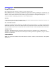
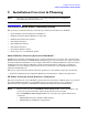
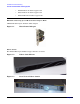
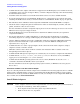
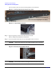
Installation Overview & Planning Overview of the HP Fabric Clustering System • AB346A HP 5m 4x Fabric Copper Cable • AB353A HP 7m 4x Fabric Copper Cable • AB347A HP 10m 4x Fabric Copper Cable HP Fabric Clustering System Host Channel Adapter (HCA) AB286A HP PCI-X 2-port 4X Fabric (HPC) Adapter Figure 1-1 Host Channel Adapter Fabric Switch The AB291A HP 12-port 4X Fabric Copper Switch is as follows: Figure 1-2 Fabric Switch Front Figure 1-3 Rear View of Fabric Switch 4 Chapter 1
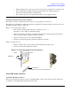
Installation Overview & Planning Installing HP Fabric Clustering System Figure 1-4 Stylized View of Switch Connectors Console Port Power Plug Fabric Switch Cluster Connections Ethernet Management Port System Status LEDs Power Plug Other Product Elements Other elements of the HP Fabric product family: • HP 4X Fabric Copper Cables — AB346A (5m length) — AB353A (7m length) — AB347A (10m length) • The HP Fabric software consists of HP-UX drivers and user-space components as well as firmware on fabric
Installation Overview & Planning Installing HP Fabric Clustering System • Confirm that the fabric adapter and software is supported on the HP Integrity server and IO slot chosen, see HP Fabric Clustering System Support Matrix, available at http://www.docs.hp.com in the Networking & Communications section. • Determine where the switch is to be installed and which servers are to have an HCA installed.
Installation Overview & Planning Installing HP Fabric Clustering System • Handle adapters by the edges only. Do not touch electronic components or electrical traces. • Use the disposable grounding wrist strap provided with each adapter. Follow the instructions included with the grounding strap. • Use a suitable ground—any exposed metal surface on the computer chassis. Installing the Fabric Host Channel Adapter The adapter comes pre-configured. You do not have to set any jumpers or connectors.
Installation Overview & Planning Installing HP Fabric Clustering System Step 1. Log on to the system as root. Step 2. Insert the software media into the appropriate drive. If the software is being loaded from a CD-ROM, go to step 3; otherwise, go to step 4. The software can also be located at http://www.software.hp.com. Step 3. Mount the CD-ROM drive by using the following command at the command prompt: $ mount device_name where device_name is the name assigned to the CD-ROM drive. Step 4.
Installation Overview & Planning Installing HP Fabric Clustering System Requirements In addition to the accessories provided with the switch, you should have: • A T-10 Torx driver and a Phillips #2 screw driver. • A second person for the installation. Rack Mount Preparation Prior to mounting the switch in a rack: 1. Check the slot in the rack for 1U clearance. 2. Open the box, remove the switch, rail brackets, and parts bag. 3. Place the switch on a secure, clean surface. 4.
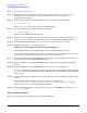
Installation Overview & Planning Installing HP Fabric Clustering System Screw locations are the same in the switch regardless of rail orientation. Figure 1-7 Rail-to-Switch Attachment Locations Attach rail to switch in the (6) locations highlighted in white. Bezel end Figure 1-8 Attach Rail to Switch Step 3. Repeat steps Steps 1 and 2 on the other side of the switch. The two sliding rails should still be unattached. Step 4. Loosely attach the switch with one screw through the front of each rail.
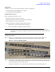
Installation Overview & Planning Installing HP Fabric Clustering System Step 5. Fit the sliding rails over the fixed rails with the flanges facing outward until the flanges meet the rack. Figure 1-10 Fit Sliding Rail over Fixed Rail Figure 1-11 Fit Sliding Rail to Rack Step 6. Attach the rails to the rack, both sides as shown in Figure 1-12. CAUTION Keep switch supported until rail is attached to the rack. Figure 1-12 Attach Sliding Rail to Rack Step 7. Securely attach all rails to the rack.
Installation Overview & Planning Installing HP Fabric Clustering System Attach Cable Guides & Cables The Fabric cables are high performance impedance-controlled cables with protective shielding, and due to the thickness and stiffness of the cables, HP recommends that Cable Guides be installed prior to attaching cables to minimize stress on the connectors for both switch and HCA cabling. The Fabric cables should be securely attached to the rack enclosure.
Installation Overview & Planning Installing HP Fabric Clustering System Attach to other Fabric devices: 1. Be sure you have attached a connector cable to the adapter. Push the connector in until you hear it click. 2. Attach the free end of the cable to a compatible fabric switch or adapter. The following table lists the cables that you can use with HP Fabric.
Installation Overview & Planning Installing HP Fabric Clustering System On-Line Addition and Replacement Operations (OL*) On-Line Addition and Replacement (OL*) of HP Fabric adapters is supported on HP Fabric Clustering System version B.11.23.02 with a couple of limitations related to replacing an HCA, see below. Replacing an HP Fabric Clustering System HCA CAUTION Do Not use an Attention Button to REPLACE an HP Fabric HCA.