
AB291A Fabric Clustering System Support Guide (12-port Switch), April 2004

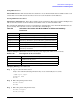


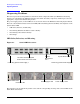
Table Of Contents
- About This Document
- 1 Introduction to Technology
- 2 Hardware Overview
- 3 Installation Planning
- 4 Installing HP Fabric Clustering System
- 5 Administration and Management
- HP-UX Host Administration and Management
- Switch Administration and Management
- CLI Overview
- Using the CLI
- Advanced Switch Setup
- Configuration, Image, and Log Files
- Configuration, Image, and Log File Overview
- File Management
- Listing Configuration, Image, and Log Files
- Viewing Configuration Files
- Viewing Log Files
- Saving Configuration Files
- Saving for System Reboot
- Saving the Backup Configuration
- Specifying the Configuration to Use at
- Saving and Copying Files
- Downloading Files to the System
- Deleting Configuration, Image, and Log Files
- Managing Log Files
- Understanding the Log Format
- Uploading Log Files
- Administering the System
- 6 Monitoring and Troubleshooting
- A Specifications
- B HP 12-Port 4X Fabric Copper Switch Commands
- Show Commands
- show arp ethernet
- show arp IB
- show authentication
- show backplane
- show boot-config
- show card
- show card-inventory
- show clock
- show config
- show fan
- show host
- show ib
- show ib sm configuration
- show ib sm multicast
- show ib sm neighbor
- show ib sm node subnet-prefix
- show ib sm partition
- show ib sm port
- show ib sm service
- show ib sm switch
- show ib-agent channel-adapter
- show ib-agent summary
- show ib-agent switch
- show ib-agent switch linear-frd-info
- show ib-agent switch all mcast-info lid
- show ib-agent switch all node-info
- show ib-agent switch all pkey-info
- show ib-agent switch port-info
- show ib-agent switch sl-vl-map
- show ib-agent switch switch-info
- show interface ib
- show interface ib sm
- show interface ib sm statistics
- show interface mgmt-ethernet
- show interface mgmt-ib
- show interface mgmt-serial
- show ip
- show location
- show logging
- show ntp
- show power-supply
- show running-status
- show sensor
- show snmp
- show system-services
- show terminal
- show trace
- show user
- show version
- IP Commands
- HP Fabric Clustering System Commands
- Administrative Commands
- action
- boot-config
- broadcast
- card
- clock
- configure
- copy
- delete
- dir
- disable
- enable
- exec
- exit
- ftp-server enable
- gateway
- help
- history
- hostname
- install
- interface
- interface mgmt-ethernet
- interface mgmt-ib
- ip
- location
- login
- logging
- logout
- more
- ntp
- ping
- radius-server
- reload
- shutdown
- snmp-server
- telnet
- terminal length
- terminal time-out
- trace
- type
- username
- who
- write
- Show Commands
- C How to Use Windows HyperTerminal
- Glossary
Chapter 6
Monitoring and Troubleshooting
Diagnosing Problems
100
Diagnosing Problems
This section provides useful guidelines to determine which component within your HP Fabric Clustering
System is at fault. Follow the LED descriptions to determine the faulty component, and then proceed to the
appropriate component troubleshooting section.
The power supply, system, and fan LEDs are located on the front of the HP Fabric Clustering System Switch.
The back contains Fabric Cluster Connection LEDs, Ethernet Management Port LEDs, and a duplicate of the
System Status LED.
• “LED Color, Behavior, and Meaning”
• “Determining Whether the HCA or Cable is Faulty”
• “Determining if the Switch is Faulty”
• “Next Steps”
LED Color, Behavior, and Meaning
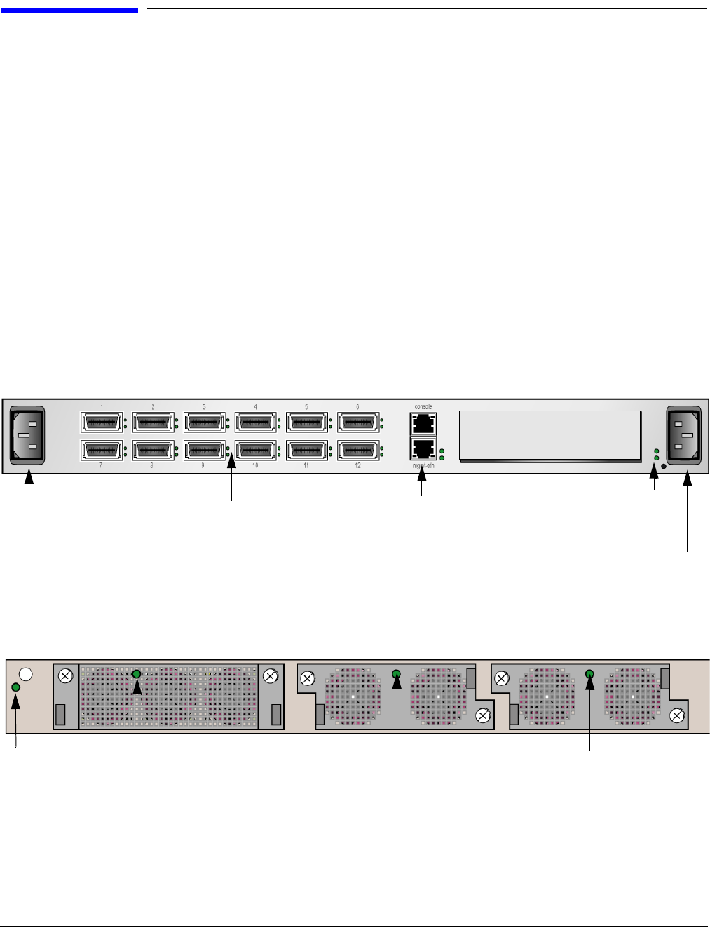
Figure 6-1 Switch LED Locations
The following sections explain the possible colors and the corresponding meaning of the various LEDs on the
Fabric HCA and switches.
HP Fabric Clustering System
Ethernet
Management
Port
System Status LEDs
System Status LED
Fan Status LED
Power Supply 2 LED Power Supply 1 LED
Power Plug powers Power Supply 1
Power Plug powers Power Supply 2
Switch Cluster Connection LEDs