
AB291A Fabric Clustering System Support Guide (12-port Switch), April 2004
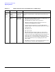
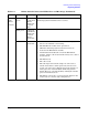
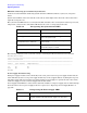
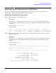
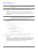
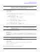

Table Of Contents
- About This Document
- 1 Introduction to Technology
- 2 Hardware Overview
- 3 Installation Planning
- 4 Installing HP Fabric Clustering System
- 5 Administration and Management
- HP-UX Host Administration and Management
- Switch Administration and Management
- CLI Overview
- Using the CLI
- Advanced Switch Setup
- Configuration, Image, and Log Files
- Configuration, Image, and Log File Overview
- File Management
- Listing Configuration, Image, and Log Files
- Viewing Configuration Files
- Viewing Log Files
- Saving Configuration Files
- Saving for System Reboot
- Saving the Backup Configuration
- Specifying the Configuration to Use at
- Saving and Copying Files
- Downloading Files to the System
- Deleting Configuration, Image, and Log Files
- Managing Log Files
- Understanding the Log Format
- Uploading Log Files
- Administering the System
- 6 Monitoring and Troubleshooting
- A Specifications
- B HP 12-Port 4X Fabric Copper Switch Commands
- Show Commands
- show arp ethernet
- show arp IB
- show authentication
- show backplane
- show boot-config
- show card
- show card-inventory
- show clock
- show config
- show fan
- show host
- show ib
- show ib sm configuration
- show ib sm multicast
- show ib sm neighbor
- show ib sm node subnet-prefix
- show ib sm partition
- show ib sm port
- show ib sm service
- show ib sm switch
- show ib-agent channel-adapter
- show ib-agent summary
- show ib-agent switch
- show ib-agent switch linear-frd-info
- show ib-agent switch all mcast-info lid
- show ib-agent switch all node-info
- show ib-agent switch all pkey-info
- show ib-agent switch port-info
- show ib-agent switch sl-vl-map
- show ib-agent switch switch-info
- show interface ib
- show interface ib sm
- show interface ib sm statistics
- show interface mgmt-ethernet
- show interface mgmt-ib
- show interface mgmt-serial
- show ip
- show location
- show logging
- show ntp
- show power-supply
- show running-status
- show sensor
- show snmp
- show system-services
- show terminal
- show trace
- show user
- show version
- IP Commands
- HP Fabric Clustering System Commands
- Administrative Commands
- action
- boot-config
- broadcast
- card
- clock
- configure
- copy
- delete
- dir
- disable
- enable
- exec
- exit
- ftp-server enable
- gateway
- help
- history
- hostname
- install
- interface
- interface mgmt-ethernet
- interface mgmt-ib
- ip
- location
- login
- logging
- logout
- more
- ntp
- ping
- radius-server
- reload
- shutdown
- snmp-server
- telnet
- terminal length
- terminal time-out
- trace
- type
- username
- who
- write
- Show Commands
- C How to Use Windows HyperTerminal
- Glossary
Chapter 6
Monitoring and Troubleshooting
Diagnosing Problems
105
The following command can be used on the switch to show power supply status from the CLI, and shows an
example of a failed Power Supply.
HP-IB# show power
============================================================================
Power-supply Information
============================================================================
ps type oper-status utilization voltage
----------------------------------------------------------------------------
1 AC up 55 12
2 AC failure na 12
NOTE It is possible that with a failed power supply, the System Status LED is yellow, and the Power
Supply LED stays green.
Fan Troubleshooting
The fan status light is located on the front in the middle of the fan tray, and the LED is visible through the
mesh of the bezel. The fan module contains three fans. The system requires at least two fans to remain
operational. If the fan needs to be replaced, see “Replacing a Fan Tray” on page 123.
The following command example can be used on the switch to determine individual fan status from the CLI.
HP-IB> show fan
========================================================================
Fan Information
========================================================================
fan oper-status speed
------------------------------------------------------------------------
1 up 80
2 up 68
3 up 74
green (AC OK) On (green) indicates AC input is present. Off indicates AC
input is not present.
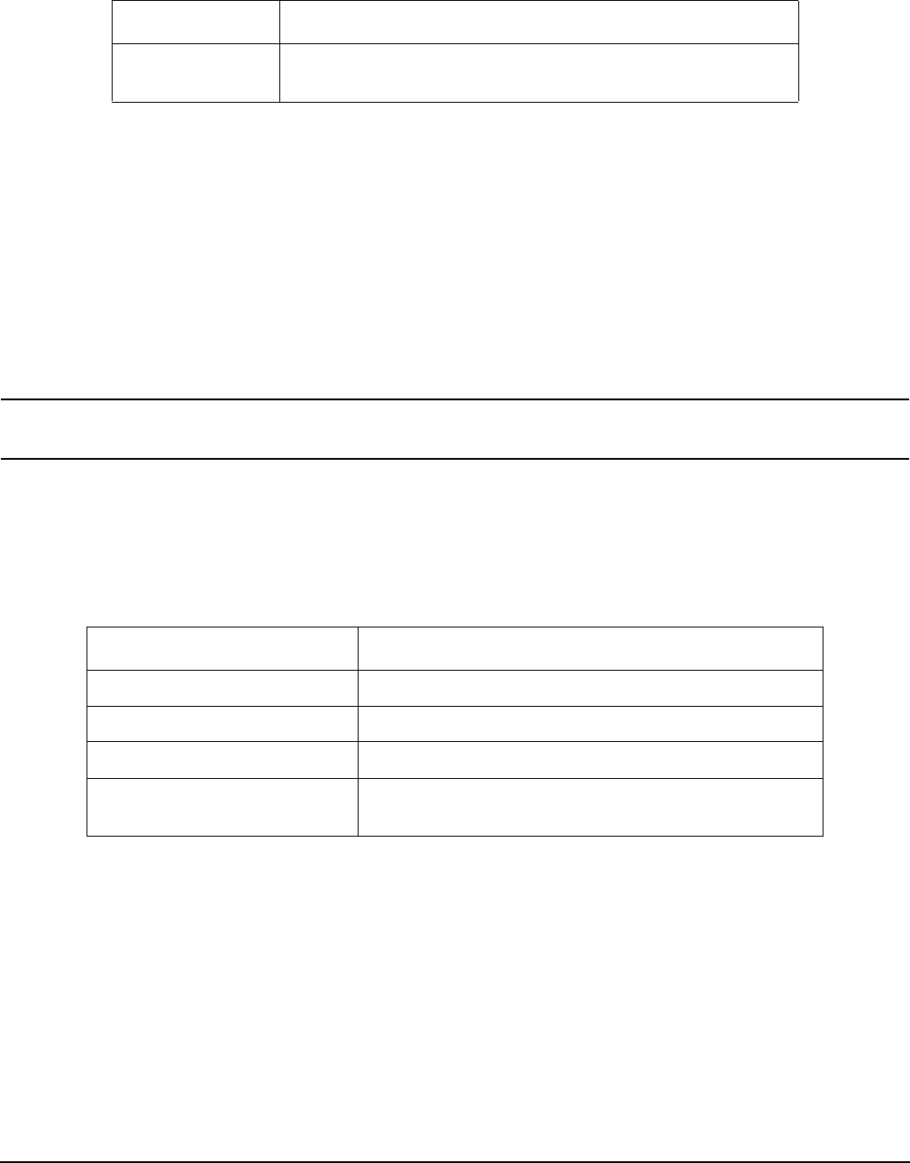
Table 6-4 Fan LED Interpretation
color indication
green Blowers running with no detected errors.
yellow Fan error detected.
off No system power or LED failure.
slow blink, alternating
green/yellow (4 sec. interval)
LED test following application of power (16 seconds).
Table 6-3 Interpreting the Power Supply LEDs (Continued)
color description