
AB291A Fabric Clustering System Support Guide (12-port Switch), April 2004
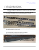
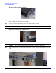
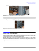
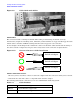
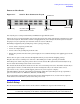


Table Of Contents
- About This Document
- 1 Introduction to Technology
- 2 Hardware Overview
- 3 Installation Planning
- 4 Installing HP Fabric Clustering System
- 5 Administration and Management
- HP-UX Host Administration and Management
- Switch Administration and Management
- CLI Overview
- Using the CLI
- Advanced Switch Setup
- Configuration, Image, and Log Files
- Configuration, Image, and Log File Overview
- File Management
- Listing Configuration, Image, and Log Files
- Viewing Configuration Files
- Viewing Log Files
- Saving Configuration Files
- Saving for System Reboot
- Saving the Backup Configuration
- Specifying the Configuration to Use at
- Saving and Copying Files
- Downloading Files to the System
- Deleting Configuration, Image, and Log Files
- Managing Log Files
- Understanding the Log Format
- Uploading Log Files
- Administering the System
- 6 Monitoring and Troubleshooting
- A Specifications
- B HP 12-Port 4X Fabric Copper Switch Commands
- Show Commands
- show arp ethernet
- show arp IB
- show authentication
- show backplane
- show boot-config
- show card
- show card-inventory
- show clock
- show config
- show fan
- show host
- show ib
- show ib sm configuration
- show ib sm multicast
- show ib sm neighbor
- show ib sm node subnet-prefix
- show ib sm partition
- show ib sm port
- show ib sm service
- show ib sm switch
- show ib-agent channel-adapter
- show ib-agent summary
- show ib-agent switch
- show ib-agent switch linear-frd-info
- show ib-agent switch all mcast-info lid
- show ib-agent switch all node-info
- show ib-agent switch all pkey-info
- show ib-agent switch port-info
- show ib-agent switch sl-vl-map
- show ib-agent switch switch-info
- show interface ib
- show interface ib sm
- show interface ib sm statistics
- show interface mgmt-ethernet
- show interface mgmt-ib
- show interface mgmt-serial
- show ip
- show location
- show logging
- show ntp
- show power-supply
- show running-status
- show sensor
- show snmp
- show system-services
- show terminal
- show trace
- show user
- show version
- IP Commands
- HP Fabric Clustering System Commands
- Administrative Commands
- action
- boot-config
- broadcast
- card
- clock
- configure
- copy
- delete
- dir
- disable
- enable
- exec
- exit
- ftp-server enable
- gateway
- help
- history
- hostname
- install
- interface
- interface mgmt-ethernet
- interface mgmt-ib
- ip
- location
- login
- logging
- logout
- more
- ntp
- ping
- radius-server
- reload
- shutdown
- snmp-server
- telnet
- terminal length
- terminal time-out
- trace
- type
- username
- who
- write
- Show Commands
- C How to Use Windows HyperTerminal
- Glossary
Installing HP Fabric Clustering System
Switch Setup
Chapter 4
35
Power on the chassis
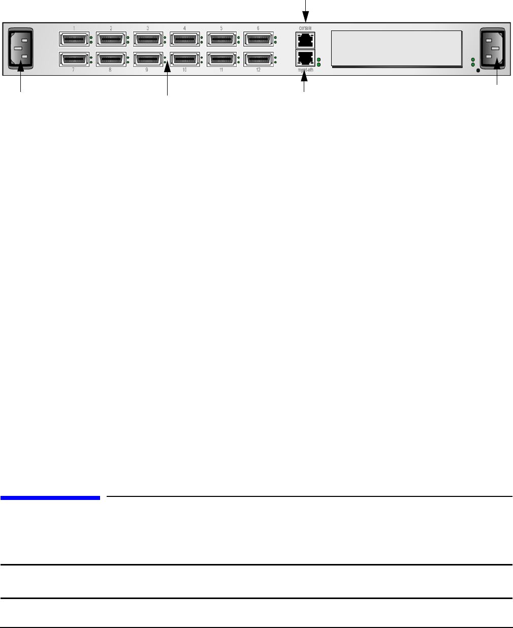
Figure 4-11 Switch - Rear Connection Layout
Use only the power cable provided with your 4X Fabric Copper Switch system.
Inspect the power cord and determine if it provides the proper plug and is appropriately certified for use with
your electrical system. Discard the cord if it is inappropriate for your country’s electrical system and obtain
the proper cord, as required by your national electrical codes or ordinances.
Grounding is supplied by the ground-prong on the 3-prong power plug.
• Do not attach a separate ground cable.
• Do not use adapter plugs.
• Do not remove the ground prong from the cable.
• Ensure the ground connection on the power supply is correct and functioning before applying power to the
chassis.
Remove the two power cords, UL rated 10 Amps/125 VAC or greater, from the shipping package.
Plug the other end of each AC power cable into a 90-132VAC power outlet operating at 47-63Hz.
Insert the power cords to the power jacks on the rear of the chassis. The system will automatically boot up.
You can watch the running status via the serial console.
The chassis automatically starts and boots. Use the correct external power-source. Attach the chassis only to
approved power sources, as indicated by the electrical ratings label. If you are unsure of the correct
power-source to use, contact your HP support personnel or your local power company.
Check the LEDs on the front of the Fabric Copper Switch. When the system first powers up, it performs a
power-on self test. Refer to “LED Color, Behavior, and Meaning”.
Because the Fabric Copper Switch is designed to provide uninterrupted service, it does not have separate
on/off switches. To turn off the system, remove the power cords.
Switch Setup
The information in this section focuses on the software and firmware aspects of the initial set-up.
NOTE The HP Fabric Clustering System Switch may be used without being managed, however HP
recommends configuring an IP address on the Ethernet Management port as detailed below.
Power Plug
Power Plug
Console Port
Ethernet
Management
Port
HP Fabric Clustering System
Switch Cluster Connection