AB378A Fibre Channel Mass Storage Adapter Installation Guide HP-UX Storage Manufacturing Part Number: AB378-96001 E0512 Printed in the US © Copyright 2005 Hewlett Packard Development Company L.P.
Legal Notices The information in this document is subject to change without notice. Hewlett-Packard makes no warranty of any kind with regard to this manual, including, but not limited to, the implied warranties of merchantability and fitness for a particular purpose. Hewlett-Packard shall not be held liable for errors contained herein or direct, indirect, special, incidental or consequential damages in connection with the furnishing, performance, or use of this material.
Contents 1. Fibre Channel Adapter Installation Supported Configurations . . . . . . . . . . . . . . . . . . . . . . . . . . . . . . . . . . . . . . . . . . . . . . . . . . . . . . . . . . . . . . 5 Superdome Installation . . . . . . . . . . . . . . . . . . . . . . . . . . . . . . . . . . . . . . . . . . . . . . . . . . . . . . . . . . . . . . . . 5 Installation Prerequisites . . . . . . . . . . . . . . . . . . . . . . . . . . . . . . . . . . . . . . . . . . . . . . . . . . . . . . . . . . . . . .
Contents 4
1 Fibre Channel Adapter Installation This chapter contains installation prerequisites, guidelines, and procedures for each host bus adapter. Thank you for purchasing HP I/O Cards If you are installing an HP I/O card as an add-in device, please review this document before attempting installation. If this card was factory installed in your server, you can skip to the Verifying Installation section. HP welcomes your input. Please email us at: netinfo_feedback@cup.hp.
Fibre Channel Adapter Installation Important Patches and Updates • Verify the following product contents: — Grounding wrist strap — Fibre Channel driver software media (included with OS or application CD) — Fibre Channel host bus adapter with an optical port protector attached (not included with all adapters). • Verify the cabling requirements: — Cable map (optional) — Fiber optic cable terminated with a duplex LC connector. Cable must be 50 or 62.5 micron multimode cable.
Fibre Channel Adapter Installation Hardware Installation 5. In the Specify Source window, change the Source Host Name if necessary. Enter the mount point of the drive in the Source Depot Path field and click the OK button to return to the Software Selection window. (You can click the Help button to get more information). 6. Select the appropriate software bundle, depending on your adapter. 7. Select Mark for Install from the Actions menu. 8.
Fibre Channel Adapter Installation Hardware Installation IMPORTANT Superdome systems are not intended for access by users. HP recommends that Superdome systems only be opened by a qualified HP engineer. Failure to observe this requirement can invalidate any support agreement or warranty to which the system owner might otherwise be entitled.
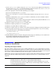
Fibre Channel Adapter Installation Attach to Fibre Channel Devices Figure 1-1 AB378A Single Port Fibre Channel Adapter and Port WWN The N_Port Port World Wide Name (WWN) is printed on the bulkhead. Attach to Fibre Channel Devices 1. Be sure you have removed the Fibre Channel host bus adapter’s optical port protector (if included). 2. Be sure you have attached a connector cable to the Fibre Channel host bus adapter. Align the slotted plug with the keyed connector.
Fibre Channel Adapter Installation Verify the Fibre Channel Adapter Installation The following table lists the Fibre Channel cables that you can use with the AB378A Fibre Channel Host Bus Adapter.
Fibre Channel Adapter Installation LED Interpretation If the correct driver is installed, but the adapter does not show in the ioscan output, the driver is not recognizing the adapter. Contact HP for assistance.
Fibre Channel Adapter Installation Obtaining Card Information after Installation N_Port N_Port Switch Switch Node Port Port Node World Wide Name = 0x50060b00002ae88b World Wide Name = 0x50060b00002ae88a World Wide Name = 0x200a0060691026e2 World Wide Name = 0x10000060691026e2 Driver state = ONLINE Hardware Path is = 0/0/10/1/0 Maximum Frame Size = 2048 Driver-Firmware Dump Available = NO Driver-Firmware Dump Timestamp = N/A Driver Version = @(#) libfcd.a HP Fibre Channel ISP 23xx & 24xx Driver B.11.23.
Fibre Channel Adapter Installation Verifying Connectivity fcp 8 ext_bus 44 0/0/10/1/0.1 fcd_fcp 0/0/10/1/0.1.17.0.0 CLAIMED INTERFACE fcd_vbus CLAIMED FCP Domain INTERFACE target 135 0/0/10/1/0.1.17.0.0.0 tgt CLAIMED DEVICE disk 867 0/0/10/1/0.1.17.0.0.0.0 sdisk CLAIMED DEVICE /dev/dsk/c44t0d0 disk 871 0/0/10/1/0.1.17.0.0.0.
Fibre Channel Adapter Installation Interpreting Hardware Paths Figure 1-2 Example of a Hardware Path for a Direct Fabric Attach Device Adapter Domain Area Port Bus Target LUN 0/1/2/0.1.19.255.0.0.0 Figure 1-3 Example of a Hardware Path for a Private Loop Device Adapter Domain Area Port Bus Target LUN 0/1/2/0.8.0.255.0.1.
Fibre Channel Adapter Installation Interpreting Hardware Paths Table 1-4 (Continued) Fibre Channel Topology of HBA Field Value Information Direct Fabric Attach Port Bus Private Loop The value depends on the Fibre Channel topology of the HBA and the target device, and on the LUN addressing method used. For LUNs with Peripheral Device Addressing, the value of this field is always 255. For LUNs with Peripheral Device Addressing, the value of this field is always 255.
Fibre Channel Adapter Installation Interpreting Hardware Paths NOTE Fibre Channel devices can connect to a Fabric using either Direct Fabric Attach or Public Loop. Different devices may have different types of connections to the same Fabric, for example an HBA may have a Direct Fabric Attach connection to the Fabric, while an array has a Public Loop connection to the same Fabric.
A Technical Specifications and Regulatory Information AB378A Technical Specifications Performance Characteristics Local bus mode and speed PCI-X 266MHz, PCI-X 133MHz, PCI-X 66MHz, PCI 66MHz, PCI 33MHz Connectivity Single port Fibre Channel, multi-mode short-wave optical link Link Speed 4Gbps / 2Gbps / 1Gbps Link Distance 4Gbps : 150m; 2Gbps : 300m; 1Gbps : 500m Over 50/125um multi-mode fiber optic cable Connector One LC Duplex Connector Bus Slot 3.
Technical Specifications and Regulatory Information FCC Statement (For U.S.A.) FCC Statement (For U.S.A.) Federal Communications Commission Radio Frequency Interference Statement WARNING This device complies with Part 15 of the FCC rules. Operation is subject to the following two conditions: (1) This device may not cause harmful interference and (2) this device must accept any interference received, including interference that might cause undesired operation.
Technical Specifications and Regulatory Information VCCI (Japan) (PCI Card Only) VCCI (Japan) (PCI Card Only) This equipment complies with the Class A category for information technology equipment based on the rules of Voluntary Control Council for Interference by Information Technology Equipment. When used in a residential area, radio interference may be caused. In this case, the user may be required to take appropriate corrective actions.
Technical Specifications and Regulatory Information Laser Safety Statements CAUTION The optical transceiver provided on the network interface card contains a laser system and is classified as a “Class 1 Laser Product” per EN 60825-1, Safety of Laser products. Class 1 laser products are considered safe and do not pose a biological hazard if used within the data sheet limits and instructions.
Technical Specifications and Regulatory Information AB378A Declaration of Conformity AB378A Declaration of Conformity Appendix A 21
Technical Specifications and Regulatory Information AB378A Declaration of Conformity 22 Appendix A
Technical Specifications and Regulatory Information AB378A Declaration of Conformity Appendix A 23