AB379B Fibre Channel Mass Storage Adapter Installation Guide HP-UX and OpenVMS Storage Manufacturing Part Number: AB379-96004 February 2007 Printed in the US © Copyright 2007 Hewlett Packard Development Company L.P.
Legal Notices The information in this document is subject to change without notice. Hewlett-Packard makes no warranty of any kind with regard to this manual, including, but not limited to, the implied warranties of merchantability and fitness for a particular purpose. Hewlett-Packard shall not be held liable for errors contained herein or direct, indirect, special, incidental or consequential damages in connection with the furnishing, performance, or use of this material.
Contents 1. Fibre Channel Adapter Installation for HP-UX Prerequisites . . . . . . . . . . . . . . . . . . . . . . . . . . . . . . . . . . . . . . . . . . . . . . . . . . . . . . . . . . . . . . . . . . . . . . . . 5 Important Patches and Updates . . . . . . . . . . . . . . . . . . . . . . . . . . . . . . . . . . . . . . . . . . . . . . . . . . . . . . . . . 6 Installing Driver Software. . . . . . . . . . . . . . . . . . . . . . . . . . . . . . . . . . . . . . . . . . . . . . . . . . . . . . . . . . . . . .
Contents 4
1 Fibre Channel Adapter Installation for HP-UX This chapter contains installation prerequisites, guidelines, and procedures for the AB379B host bus adapter.
Fibre Channel Adapter Installation for HP-UX Important Patches and Updates • Verify that you have the following items: — Grounding wrist strap — Fibre Channel driver software media (included with the OS or application CD) — Fibre Channel host bus adapter with an optical port protector attached (not included with all adapters) • Verify that you have the following cabling items: — Fiber optic cable terminated with a duplex LC connector.
Fibre Channel Adapter Installation for HP-UX Installing Driver Software Install all driver software and dependency patches before you install the adapter. See the FibrChanl-01 (fcd) Fibre Channel Mass Storage Driver Release Notes available at: http://docs.hp.com for details. To load the driver from a CD-ROM, do the following: Step 1. Log in to the system as root. Step 2. Insert the CD into the CD drive. Step 3. Mount the CD using the following command: mount /dev/dsk/ / Step 4.
Fibre Channel Adapter Installation for HP-UX Installing Adapter Hardware Installing Adapter Hardware The Online Addition and Replacement feature, OLAR for HP-UX 11i v1, or OL* for HP-UX 11i v2 and later HP-UX releases, enables PCI host bus adapters to be added or replaced without shutting down and rebooting the system, and without adversely affecting other system components. The system hardware uses slot-specific power control, combined with HP-UX operating system support, to enable these features.
Fibre Channel Adapter Installation for HP-UX Installing Adapter Hardware Step 1. Install all driver software and dependent patches. Step 2. Shut down the system. Step 3. Install the adapter in an available PCI-X slot. Step 4. Attach fiber cabling to the adapter. All Fibre Channel host bus adapters that use the FCD driver use a cable terminated with an LC connector. Installing the Host Bus Adapter Step 1.
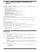
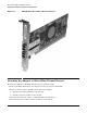
Fibre Channel Adapter Installation for HP-UX Attaching the Adapter to Other Fibre Channel Devices Figure 1-1 AB379B Dual Port Fibre Channel Adapter Attaching the Adapter to Other Fibre Channel Devices To attach the adapter to other Fibre Channel devices, follow these steps: 1. Remove the Fibre Channel host bus adapter’s optical port protector (if included). 2. Attach a connector cable to the Fibre Channel host bus adapter. a. Align the slotted plug with the keyed connector. b.
Fibre Channel Adapter Installation for HP-UX Verifying the Fibre Channel Adapter Installation Table 1-1 lists the Fibre Channel cables that you can use when connecting devices to Fibre Channel host bus adapters. Be sure to use LC-LC or LC-SC cables for the Fibre Channel host bus adapters which use the FCD driver.
Fibre Channel Adapter Installation for HP-UX LED Interpretation LED Interpretation Table 1-3 AB379B LED Interpretation Table Yellow LED (4 Gbps) Green LED (2 Gbps) Amber LED (1 Gbps) Power OFF OFF OFF OFF Card doesn’t have power Power ON ON ON ON Card powered on and not initialized Power ON 1 Flash/s 1 Flash/s 1 Flash/s After firmware initialization AWAITING LINK-UP All flashing at the same time Firmware Fault 2 Flash/s 2 Flash/s 2 Flash/s All three LEDs flash in continuous sequence
Fibre Channel Adapter Installation for HP-UX Obtaining Card Information after Installation Driver-Firmware Dump Available = NO Driver-Firmware Dump Timestamp = N/A Driver Version = @(#) libfcd.a HP Fibre Channel ISP 23xx & 24xx Driver B.11.23.06 /ux/core/isu/FCD/kern/src/common/wsio/fcd_init.c:Sep 5 2006,19:57:2 This card is capable of running at higher bus speeds, up to 266Mhz. The speed of the server slot determines the maximum speed. The actual speed is displayed as the PCI Mode.
Fibre Channel Adapter Installation for HP-UX Verifying Connectivity Verifying Connectivity Once your HP Fibre Channel Mass Storage software and hardware is installed and running, follow these steps to verify connectivity: Step 1. Check the state of all Fibre Channel hardware and interfaces. Enter the ioscan command and verify that the Hardware State and the HW-Interface State are CLAIMED. If the Fibre Channel device file has not been created, enter the following commands: # insf -e # ioscan -f Step 2.
Fibre Channel Adapter Installation for HP-UX Interpreting Legacy Hardware Paths (HP-UX 11i v1 and 11i v2) Table 1-4 describes each field in the hardware path. Table 1-4 Hardware Path Field Descriptions Fibre Channel Topology of HBA Field Value Fabric Topologies Private Loop Adapter The hardware path of the Fibre Channel adapter through which the Logical Unit Number (LUN) is seen. For multiport adapters, this field describes a specific port on the adapter.
Fibre Channel Adapter Installation for HP-UX Interpreting Legacy Hardware Paths (HP-UX 11i v1 and 11i v2) Table 1-4 Hardware Path Field Descriptions (Continued) Fibre Channel Topology of HBA Field Target Value Depends on the Fibre Channel topology and the LUN addressing method used. Fabric Topologies Private Loop For LUNs with Peripheral Device Addressing, the value of this field is the lower 4-bits of the third byte of the N_Port ID of the target device.
Fibre Channel Adapter Installation for HP-UX Interpreting Lunpath Hardware Paths (HP-UX 11i v3) Interpreting Lunpath Hardware Paths (HP-UX 11i v3) Lunpath hardware paths are a new representation of hardware paths introduced on HP-UX 11i v3, as part of the new agile representation of mass storage devices. For more details, please refer to the Next Generation Mass Storage Stack HP-UX 11i v3 white paper at http://docs.hp.com/en/netsys.html#Storage%20Area%20Management .
Fibre Channel Adapter Installation for HP-UX Interpreting Lunpath Hardware Paths (HP-UX 11i v3) Target Node World Wide Name = 0x500805f300083890 The LUN address for a Fibre Channel device is a 64-bit LUNid.
Fibre Channel Adapter Installation for HP-UX Interpreting Lunpath Hardware Paths (HP-UX 11i v3) The controller, target, and lun values are extracted from the LUN id as shown in the table: Table 1-8 Controller (7 bits) Target (4 bits) 0-63 0-15 LUN (3 bits) 0-7 To convert a lunpath hardware path to a legacy hardware path, use the scsimgr get_info command on the target’s hardware path to display the port_id, which contains the domain, area, and port values.
Fibre Channel Adapter Installation for HP-UX Interpreting Lunpath Hardware Paths (HP-UX 11i v3) 20 Chapter 1
2 Fibre Channel Adapter Installation for OpenVMS This chapter contains installation prerequisites, guidelines, and procedures for the AB379B host bus adapter.
Fibre Channel Adapter Installation for OpenVMS Installing Driver Software Installing Driver Software The driver for the AB379B Fibre Channel Host Bus Adapter is included in the installation of OpenVMS Version 8.3 and later OpenVMS releases. To check for the latest software patches, search for OpenVMS at: http://www.itrc.hp.com. Installing Adapter Hardware The Online Addition and Replacement feature is not supported in OpenVMS.
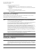
Fibre Channel Adapter Installation for OpenVMS Installing Adapter Hardware Figure 2-1 AB379B Dual Port Fibre Channel Adapter The N_Port Port World Wide Name (WWN) is printed on the bulkhead.
Fibre Channel Adapter Installation for OpenVMS Attaching the Adapter to Other Fibre Channel Devices Attaching the Adapter to Other Fibre Channel Devices To attach the adapter to other Fibre Channel devices, follow these steps: 1. Remove the Fibre Channel host bus adapter’s optical port protector (if included). 2. Attach a connector cable to the Fibre Channel host bus adapter. a. Align the slotted plug with the keyed connector. b. Push the connector in until you hear it click. 3.
Fibre Channel Adapter Installation for OpenVMS Verifying the Fibre Channel Adapter Installation Error count 0 Owner process ““ Owner process ID 00000000 Reference count 0 Current preferred CPU Id 1 Current Interrupt CPU Id 1 FC Port Name 5006-0B00-003B-48F6 Operations completed Owner UIC Dev Prot Default buffer size Fastpath FC Node Name 2980 [SYSTEM] S:RWPL,O:RWPL,G,W 0 1 5006-0B00-003B-48F7 4.
Fibre Channel Adapter Installation for OpenVMS Additional Configuration Information SDA> FC SHOW STDT SYS$PGQDRIVER - QLogic ISP24xx - FGA0 - SPDT 8272B100 - STDTs ------------------------------------------------------------| STDT Cred STDT FC-LA Port Name LID PortID | Stat I/Os -------- ----- ------------------- --- ------ + ---- ---82B84BC0 00010 5000.1FE1.5001.A3EC 091 013200 | 0001 0000 82B88E80 00015 5000.1FE1.0015.2D08 097 020800 | 0001 0000 82B7CE00 00006 5000.1FE1.0015.
A Technical Specifications and Regulatory Information AB379B Technical Specifications Table A-1 Performance Characteristics Local bus mode and speed PCI-X 266MHz, PCI-X 133MHz, PCI-X 66MHz, PCI 66MHz, PCI 33MHz Connectivity Dual port Fibre Channel, multi-mode short-wave optical link Link Speed 4 Gbps / 2 Gbps / 1 Gbps Link Distance 4Gbps : 150m; 2Gbps : 300m; 1Gbps : 500m Over 50/125um multi-mode fiber optic cable Connector Two LC Duplex Connectors Bus Slot 3.
Technical Specifications and Regulatory Information FCC Statement (For U.S.A.) FCC Statement (For U.S.A.) Federal Communications Commission Radio Frequency Interference Statement WARNING This device complies with Part 15 of the FCC rules. Operation is subject to the following two conditions: (1) This device may not cause harmful interference and (2) this device must accept any interference received, including interference that might cause undesired operation.
Technical Specifications and Regulatory Information VCCI (Japan) (PCI Card Only) VCCI (Japan) (PCI Card Only) This equipment complies with the Class A category for information technology equipment based on the rules of Voluntary Control Council for Interference by Information Technology Equipment. When used in a residential area, radio interference may be caused. In this case, the user may be required to take appropriate corrective actions.
Technical Specifications and Regulatory Information Laser Safety Statements CAUTION The optical transceiver provided on the network interface card contains a laser system and is classified as a “Class 1 Laser Product” per EN 60825-1, Safety of Laser products. Class 1 laser products are considered safe and do not pose a biological hazard if used within the data sheet limits and instructions.
Technical Specifications and Regulatory Information AB379B Declaration of Conformity AB379B Declaration of Conformity Appendix A 31
Technical Specifications and Regulatory Information AB379B Declaration of Conformity 32 Appendix A