AD193A/AD194A PCI-X 4 Gigabit Fibre Channel and Gigabit Ethernet / Combination Card Overview HP-UX Networking HP 9000 and HP Integrity Systems Manufacturing Part Number : E1206 U.S.A. © Copyright 2006 Hewlett-Packard Development Company L.P.
Legal Notices The information in this document is subject to change without notice. Hewlett-Packard makes no warranty of any kind with regard to this manual, including, but not limited to, the implied warranties of merchantability and fitness for a particular purpose. Hewlett-Packard shall not be held liable for errors contained herein or direct, indirect, special, incidental or consequential damages in connection with the furnishing, performance, or use of this material.
Hardware and Software Installation Procedure Step 1: Access the system card bay Hardware and Software Installation Procedure These instructions apply to AD193A/AD194A 4 Gigabit Fibre Channel and Gigabit Ethernet combination cards.
Hardware and Software Installation Procedure Step 3: Connect the card to the network • Secure the card and reassemble the system. Step 3: Connect the card to the network • Attach the connector from a LAN cable to the card (Figure 1 on page 11). Do the same for the second port. For 1000Base-T, cabling must be Cat 5 UTP or better with RJ-45 connectors. For operating distances, refer to the “Cable Specifications” section of this document. Note: LAN A is the bottom RJ-45 connector.
Hardware and Software Installation Procedure Step 6: Install the latest software. or B.11.23 The version must be B.11.11 for 11i v1 or B.11.23 for 11i v2. • Check the Release Notes for IEther-00 and FibrChanl-01 to see if you need to install any appropriate patches for your system. Release Notes are available on the Web at http://docs.hp.com under Networking and Communications. Step 6: Install the latest software. • Load the software media into the appropriate drive.
Hardware and Software Installation Procedure Step 9: Verify the LAN installation fc 5 1/0/8/1/0/4/1 fcd CLAIMED INTERFACE HP AD194-60001 PCI/PCI-X 2-port 4Gb FC/2-port 1000B-T Combo Adapter (FC Port 2) The last two digits of the hardware path (third column) reflect the path of each port. Both ports need to show as CLAIMED here. • Verify that all devices you attached to the fibre channel card are listed in the ioscan output.
Hardware and Software Installation Procedure Optional Step: Configure Jumbo Frames Size (Jumbo frames are supported only at 1000 Mbit/s) Optional Step: Configure Jumbo Frames Size (Jumbo frames are supported only at 1000 Mbit/s) • Jumbo frames for the iether driver on HP-UX 11i v1 and HP-UX 11i v2 of September 2004 (or later) have an MTU in the range of 1501 to 9000 bytes.
Hardware and Software Installation Procedure For Further Information Maintenance and troubleshooting information about the iether Gigabit Ethernet driver used in this product is located in the Ethernet Support Guide. There is maintenance and troubleshooting information about the fcd Fibre Channel driver used in this product in the HP Fibre Channel Mass Storage Adapters Support Guide. There is also a Support Matrix for Gigabit Ethernet and a separate one for Fibre Channel.
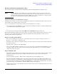
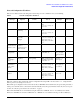
Hardware and Software Installation Procedure Network Configuration Worksheet Network Configuration Worksheet Fill out one worksheet for the networking data of each LAN port on the combination card you are installing. Table 2 Data Type Network Configuration Worksheet Required/ Optional Default How to Configure (see Note 1) Example Internet Address Required 0.0.0.0 SAM or ifconfig or edit /etc/rc.config.d/ netconf 196.6.20.
Hardware and Software Installation Procedure Cable Specifications Cable Specifications Operating Distance for 1000Base-T (Copper UTP): Up to 100 meters — Cat 5 and Cat 5E Operating distances for fibre channel using multi-mode fiber optic cable are as follows: Description (Fibre Channel) Rate Operating Distance 50/125 micron MMF 4 Gbits/s 150 meters (492 ft) 50/125 micron MMF 2 Gbits/s 300 meters (984 ft) 50 micron MMF 1 Gbits/s 500 meters (1640 ft) Available HP Fiber Optic Cables: LC-LC C7524A
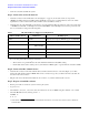
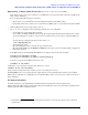
Hardware and Software Installation Procedure Figure 1 AD194A PCI-X 2-Port 4 Gb FC/ 2-Port 1000B-T Combination Card Port 1 Speed LEDS (Port 1) Fibre Channel Connectors (Duplex LC) Speed LEDS (Port 2) LED1 (4 Gbit/s) LED2 (1 or 2 Gbit/s) LED2 LED1 Port 2 Activity/Link LEDs Flashing = Data traffic Solid = Active link OFF = No link LAN A } 1000Base-T Connectors (RJ-45) LAN B PCI-X 133 MHz Speed LEDs Off = 10 Mbit/s Green = 100 Mbit/s Yellow = 1000 Mbit/s The following table shows the meaning of th
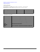
Hardware and Software Installation Procedure Table 3 Card State LED Patterns LED 1 Yellow (4Gbit/s) LED 2 Amber/Green (2/1Gbit/s) Meaning Firmware Fault 2 Flash/s Amber 2 Flash/s All 3 LEDs flash in continuous sequence 1Gbps Link UP/ACT Off Amber On 5 Flash/s Online I/O Activity 2Gbps Link UP/ACT Off Green On 5 Flash/s Online I/O Activity 4Gbps Link UP/ACT On 5 Flash/s Off Online I/O Activity 12
Hardware and Software Installation Procedure Features Features The AD193A/AD194A PCI-X Combination cards have the following features: • PCI-X 133 MHz capable card. It can operate at 32-bit or 64-bit compatible modes and is supported in the following frequencies: PCI 66, PCI-X 66, and PCI-X 133. Best performance is achieved by putting the card in a “dual-rope” PCI-X 133 slot. To identify which slots are the dual rope slots in a particular system, please refer to the hardware users’ guide for each system.
Hardware and Software Installation Procedure Features — FC-FLA — FC-PLDA — FC-PI • 14 Supports PCI-X error handling. This feature provides a system with improved fault-tolerance. PCI-X Error Handling allows an HP-UX system to avoid a Machine Check Abort (MCA) or a High Priority MachineCheck (HPMC), if a PCI-X error occurs (for example, a parity error).
Physical, Environmental and Regulatory Information Card Physical and Environmental Specifications A Physical, Environmental and Regulatory Information This appendix contains regulatory statements for the United States, Canada, Australia/New Zealand, Japan, and the European community. Card Physical and Environmental Specifications Following are the product physical and environmental specifications of the AD193A/AD194A PCI-X 2-Port 4Gigabit Fibre Channel and 2-Port Gigabit Ethernet Combination Card.
Physical, Environmental and Regulatory Information FCC Statement (For U.S.A.) Maximum kV (if less than 25 kV) with no component damage 25 Operating Altitude 3,000 meters (9900) ft Non-operating Altitude 4,500 meters (14850 ft) Electromagnetic Compatibility This document contains regulatory statements for the United States and the European community. FCC Statement (For U.S.A.
Physical, Environmental and Regulatory Information EMI Statement (European Community) EMI Statement (European Community) NOTE This is a Class A product. In a domestic environment, this product may cause radio interference, in which case you may be required to take adequate measures. Laser Safety Statements Laser Safety Statements - U.S.
Physical, Environmental and Regulatory Information Laser Safety Statements There are no user serviceable parts nor any maintenance required for the optical transceiver. All adjustments are made at the factory before shipment to customers. Tampering with or any attempt to modify the optical transceiver will result in voided product warranty. It may also result in improper operation of the network card circuitry and possible overstress of the laser source. Device degradation or product failure may result.