AD299A/AD355A Fibre Channel Mass Storage Adapters Installation Guide HP-UX 11i v2 Manufacturing Part Number: AD299-9001A May 2007 Printed in the US © Copyright 2007 Hewlett Packard Development Company L.P.
Legal Notices The information in this document is subject to change without notice. Hewlett-Packard makes no warranty of any kind with regard to this manual, including, but not limited to, the implied warranties of merchantability and fitness for a particular purpose. Hewlett-Packard shall not be held liable for errors contained herein or direct, indirect, special, incidental or consequential damages in connection with the furnishing, performance, or use of this material.
Contents 1. Fibre Channel Adapter Installation for HP-UX Prerequisites . . . . . . . . . . . . . . . . . . . . . . . . . . . . . . . . . . . . . . . . . . . . . . . . . . . . . . . . . . . . . . . . . . . . . . . . 6 Important Patches and Updates . . . . . . . . . . . . . . . . . . . . . . . . . . . . . . . . . . . . . . . . . . . . . . . . . . . . . . . . . 7 Installing Driver Software. . . . . . . . . . . . . . . . . . . . . . . . . . . . . . . . . . . . . . . . . . . . . . . . . . . . . . . . . . . . . .
Contents 4
1 Fibre Channel Adapter Installation for HP-UX This chapter contains installation prerequisites, guidelines, and procedures for the AD299A and AD355A PCI Express host bus adapters.
Fibre Channel Adapter Installation for HP-UX Prerequisites Prerequisites Before installing the adapter, follow these steps: Step 1. Verify compliance with supported configurations using the HP Fibre Channel Host Bus Adapter Support Matrix at: http://docs.hp.com/en/netcom.html#Fibre%20Channel Step 2. Determine if the adapter is a Customer Replaceable Unit (CRU) using the HP Fibre Channel Host Bus Adapter Support Matrix. If the adapter is not a CRU, contact your HP representative for installation assistance.
Fibre Channel Adapter Installation for HP-UX Important Patches and Updates Important Patches and Updates Review the FibrChanl-02 (fclp) Fibre Channel Mass Storage Driver for HP-UX Release Notes located at docs.hp.com for the latest patch and dependency requirements. Install all driver software and dependency patches before you install the adapter. NOTE Patches are available from http://www.software.hp.
Fibre Channel Adapter Installation for HP-UX Installing Adapter Hardware View the Install window to read processing data while the software installs. When the Status field indicates Ready, the Confirmation window opens. Step 10. Click OK. A second Confirmation window opens. Step 11. Click OK again. The Install window opens. Step 12. Click Done. The Note window opens. Step 13. Click OK in the Note window to reboot. The user interface disappears and the system reboots. Step 14.
Fibre Channel Adapter Installation for HP-UX Installing Adapter Hardware • Wait for the system to shut down completely, and then power off the system by pressing the system off button. • Ensure that the system is grounded. • Open the system to gain access to the PCIe + PCI-X hybrid backplane. • Insert the card into the highest-performance PCIe slot available. NOTE With HP-UX 11i v2, be sure to check that you are installing the card in a non-switched slot.
Fibre Channel Adapter Installation for HP-UX Attaching the Adapter to Other Fibre Channel Devices Attaching the Adapter to Other Fibre Channel Devices To attach the adapter to other Fibre Channel devices, follow these steps: 1. Remove the Fibre Channel host bus adapter’s optical port protector (if included). 2. Attach a connector cable to the Fibre Channel host bus adapter. a. Align the slotted plug with the keyed connector. b. Push the connector in until you hear it click. 3.
Fibre Channel Adapter Installation for HP-UX Verifying the Fibre Channel Adapter Installation Verifying the Fibre Channel Adapter Installation To verify that your Fibre Channel Adapter has been correctly installed, follow these steps: Step 1. Enter the following command: ioscan -f Step 2. Verify that the correct drivers appear for each installed adapter. If all drivers display, proceed to the next section, see “Verifying Connectivity” on page 17.
Fibre Channel Adapter Installation for HP-UX Verifying the Fibre Channel Adapter Installation If the ioscan output is similar to the following: fc 0/0/2/1/0 UNCLAIMED UNKNOWN HP-UX detected the adapter, but the drivers are not properly loaded. If the correct driver is installed, but the adapter does not show in the ioscan output, the driver is not recognizing the adapter. Step 3. If the ioscan output indicates a problem, contact HP for assistance.
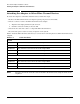
Fibre Channel Adapter Installation for HP-UX LED Interpretation LED Interpretation Table 1-2 Yellow LED AD299A/AD355A LED Interpretation Table Green LED HBA State 1 Blink ON Normal Operation (1 Gb link rate, link up) 2 Blinks ON Normal Operation (2 Gb link rate, link up) 3 Blinks ON Normal Operation (4 Gb link rate, link up) OFF Slow blink Normal (link down or not started) OFF OFF Slot Not Powered, or Adapter Card Initialization Failure ON OFF POST Failure (dead board) Slow blink OFF
Fibre Channel Adapter Installation for HP-UX Obtaining Card Information After Installation PCI Sub-system ID is = 0x7049 Chip version = 2 Firmware Version = 2.70X5 SLI-3 (Z3F2.
Fibre Channel Adapter Installation for HP-UX Obtaining Card Information After Installation Topology = PTTOPT_FABRIC Link Speed = 4Gb Local N_Port_id = 0x018500 Previous Local N_Port_id = None N_Port Node World Wide Name = 0x50060B0000FD614B N_Port Port World Wide Name = 0x50060B0000FD614A Switch Port World Wide Name = 0x208500051E360C30 Switch Node World Wide Name = 0x100000051E360C30 Driver state = ONLINE Driver Version = @(#) FCLP: PCIe Fibre Channel driver (FibrChanl-02), B.11.23.
Fibre Channel Adapter Installation for HP-UX Obtaining Card Information After Installation V I T A L P R O D U C T D A T A --------- ------------- ------- Product Description : "HP AD299A PCIe 1-port 4Gb FC HBA" Part number : "AD299-60001" Part Serial number : "JP47210016" Engineering Date Code : "A-4718" Mfd. Date : "4721" Misc. Information : "PW=7.5W; PCIe x4 Gen1" ROM Firmware version : "2.70X5 SLI-3 (Z3D2.
Fibre Channel Adapter Installation for HP-UX Verifying Connectivity Verifying Connectivity Once your HP Fibre Channel Mass Storage software and hardware is installed and running, follow these steps to verify connectivity: Step 1. Check the state of all Fibre Channel hardware and interfaces. Enter the ioscan command and verify that the Hardware State and the HW-Interface State are CLAIMED. If the Fibre Channel device file has not been created, enter the following commands: # insf -e # ioscan -f Step 2.
Fibre Channel Adapter Installation for HP-UX Interpreting Hardware Paths Interpreting Hardware Paths Example 1-1 and 1-2 illustrate the Fibre Channel hardware path format: Example 1-1 Hardware Path for a Direct Fabric Attach Device Adapter Domain Area Port Bus Target LUN 0/1/2/0.1.19.255.0.0.0 Example 1-2 Hardware Path for a Private Loop Device Adapter Domain Area Port Bus Target LUN 0/1/2/0.8.0.255.0.1.0 Table 1-3 describes each field in the hardware path.
Fibre Channel Adapter Installation for HP-UX Interpreting Hardware Paths Table 1-3 Hardware Path Field Descriptions (Continued) Fibre Channel Topology of HBA Field Value Fabric Topologies Port Depends on the Fibre Channel topology of the HBA and the target device, and on the LUN addressing method used. Bus Depends on the Fibre Channel topology of the HBA and the target device, and on the LUN addressing method used.
Fibre Channel Adapter Installation for HP-UX Firmware Updates Firmware Updates This section explains the process for updating the firmware of your Fibre Channel host bus adapter. Fibre Channel Host Bus Adapter Online Firmware Updates The Fibre Channel host bus adapters that use the fclp driver cannot be updated while the system is online, because the rom_fw_update option of the fcmsutil command is not supported for these bus adapters at this time.
Fibre Channel Adapter Installation for HP-UX Fibre Channel Device Scanning Policy Configuration for HP Integrity Systems Fibre Channel Device Scanning Policy Configuration for HP Integrity Systems Because fibre channel SANs can contain many potential boot devices, it is necessary to use an appropriate EFI device scanning policy, when booting an HP Integrity server which is connected to a SAN.
Fibre Channel Adapter Installation for HP-UX Fibre Channel Device Scanning Policy Configuration for HP Integrity Systems 9. Select one of the scanning policies from the list presented. The Boot Path from NVRAM Targets option, which is the default option, requires additional configuration in the Configure Boot Devices option in the previous menu. Using this scanning policy, you can enter a list of particular targets and LUNs that you would like the EFI driver to search for potential boot devices.
A Technical Specifications and Regulatory Information AD299A Technical Specifications Table A-1 Performance Characteristics Bus Interface PCI Express x41 PCIe Lane Speed 2.5 Gb/s Connectivity Single port Fibre Channel, multi-mode short-wave optical link Link Speed 4 Gbps / 2 Gbps / 1 Gbps Link Distance 4 Gbps : 150m; 2 Gbps : 300m; 1 Gbps : 500m Over 50/125um multi-mode fiber optic cable Connector One LC Duplex Connector Physical Length 168 mm (6.61 inches) Width 68 mm (2.
Technical Specifications and Regulatory Information AD299A Technical Specifications NOTE 24 1 PCI Express (PCIe) differs from the previous generation PCI-X bus in that it uses multiple lanes of serial links to transport data between the HBA and the system. The AD299A is a PCIe x4 Gen1 HBA. The “x4” indicates that the AD299A uses four PCIe lanes; the “Gen1” indicates that each lane is capable of transferring user data plus PCIe control data at 2.
Technical Specifications and Regulatory Information AD355A Technical Specifications AD355A Technical Specifications Table A-2 Performance Characteristics Bus Interface PCI Express x41 PCIe Lane Speed 2.5 Gb/s Connectivity Dual port Fibre Channel, multi-mode short-wave optical link Link Speed 4 Gbps / 2 Gbps / 1 Gbps Link Distance 4 Gbps : 150m; 2 Gbps : 300m; 1 Gbps : 500m Over 50/125um multi-mode fiber optic cable Connector Two LC Duplex Connectors Physical Length 168 mm (6.
Technical Specifications and Regulatory Information AD355A Technical Specifications NOTE 26 1 PCI Express (PCIe) differs from the previous generation PCI-X bus in that it uses multiple lanes of serial links to transport data between the HBA and the system. The AD355A is a PCIe x4 Gen1 HBA. The “x4” indicates that the AD355A uses four PCIe lanes; the “Gen1” indicates that each lane is capable of transferring user data plus PCIe control data at 2.
Technical Specifications and Regulatory Information FCC Statement (For U.S.A.) FCC Statement (For U.S.A.) Federal Communications Commission Radio Frequency Interference Statement WARNING This device complies with Part 15 of the FCC rules. Operation is subject to the following two conditions: (1) This device may not cause harmful interference and (2) this device must accept any interference received, including interference that might cause undesired operation.
Technical Specifications and Regulatory Information VCCI (Japan) (PCI Card Only) VCCI (Japan) (PCI Card Only) This equipment complies with the Class A category for information technology equipment based on the rules of Voluntary Control Council for Interference by Information Technology Equipment. When used in a residential area, radio interference may be caused. In this case, the user may be required to take appropriate corrective actions.
Technical Specifications and Regulatory Information Laser Safety Statements CAUTION The optical transceiver provided on the network interface card contains a laser system and is classified as a “Class 1 Laser Product” per EN 60825-1, Safety of Laser products. Class 1 laser products are considered safe and do not pose a biological hazard if used within the data sheet limits and instructions.
Technical Specifications and Regulatory Information AD299A/AD355A Declaration of Conformity AD299A/AD355A Declaration of Conformity 30 Appendix A
Technical Specifications and Regulatory Information AD299A/AD355A Declaration of Conformity Appendix A 31
Technical Specifications and Regulatory Information AD299A/AD355A Declaration of Conformity 32 Appendix A