HP 8 Internal Port SAS Controller and HP Multi-Port Internal SAS Controller Support Guide HP-UX 11i v2, 11i v3 HP Part Number: 5900-0112 Published: September 2009 Edition: 6
© Copyright 2009 Hewlett-Packard Development Company L.P. Legal Notices The information contained herein is subject to change without notice. The only warranties for HP products and services are set forth in the express warranty statements accompanying such products and services. Nothing herein should be construed as constituting an additional warranty. HP shall not be liable for technical or editorial errors or omissions contained herein.
Table of Contents Preface: About This Document .........................................................................................7 Intended Audience.................................................................................................................................7 New and Changed Documentation in This Edition...............................................................................7 Publishing History..................................................................................
Resetting the Error Counts.........................................................................................................31 Exiting drvcfg..................................................................................................................................31 Example: Adding, Viewing, and Deleting An Integrated Mirror Volume Using drvcfg.....................32 Determining the Driver ID and Ctrl ID...........................................................................................
4 Configuring and Troubleshooting the Controller Online.........................................51 Introduction..........................................................................................................................................51 Troubleshooting sasd............................................................................................................................51 The ioscan Utility...............................................................................................
Preface: About This Document This document describes how to install, configure, and troubleshoot HP internal Serial-Attached SCSI (SAS) controllers on HP-UX 11i v2 and 11i v3 platforms. The latest version of this document is available online at: http://docs.hp.com/en/netcom.html Intended Audience This document is for system and network administrators responsible for installing, configuring, and managing fault tolerant data storage.
Chapter 4 “Configuring and Troubleshooting the Controller Online” provides information on configuring and troubleshooting the HP internal SAS controllers online using the ioscan and sasmgr commands. Appendix A “Electrostatic Discharge” provides information about preventing damage due to electrostatic discharge. Appendix B “Specifications” Related Documents For more information about HP internal SAS controllers, see: http://docs.hp.com/en/netcom.
1 Controller Overview This chapter provides an overview of the SAS controller and its technology. This chapter includes the following topics: “Serial-Attached SCSI (SAS) Technology Description” (page 9) “Controller Description” (page 9) Serial-Attached SCSI (SAS) Technology Description Serial-attached SCSI (SAS) is a method for connecting computer peripheral devices that employs a serial (one bit at a time) means of digital data transfer over thin cables.
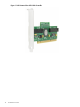
Figure 1-1 HP 8 Internal Port PCI-X SAS Controller 10 Controller Overview
Connectors and Indicators Figure 1-2 illustrates the connectors and indicator LEDs on the HP 8 Internal Port PCI-X SAS Controller. Table 1-1 describes each component. Figure 1-2 Connectors and Indicators Table 1-1 Component Descriptions Number Description 1 Heartbeat LED (green/amber). Flashing green indicates normal operation. Amber indicates that the card’s firmware has detected a fault. 2 Activity LED (green). Blinks when there is I/O activity on any port. 3 Internal 4x SAS connector, port 1.
2 Replacing a Controller This chapter provides information on replacing an HP 8 Internal Port PCI-X SAS Controller. This chapter includes the following topics: “Replacement Overview” (page 13) “Preparing the Server” (page 13) “Replacing the Controller” (page 13) “Completing the Controller Replacement” (page 14) NOTE: The HP 8 Internal Port PCI-X SAS Controller is a factory-integrated core I/O card. Online Addition, Deletion, and Replacement are not supported.
3. 4. 5. 6. 7. 8. 9. Label the connectors to the internal drive bays. The connector closest to the mounting bracket is Port 1, and the connector closest to the interior of the server is Port 2. Disconnect the cables from the PCI-X card. Depending on the server model, remove the retaining screw or open the expansion slot latch that secures the PCI-X card. Remove the card. Insert the new card into the slot, and press it firmly into place.
3 Configuring the Controller Offline The following information provides steps needed to configure the SAS controller during installation.
The drvcfg Utility This section describes in detail all of the available commands and options in the drvcfg utility. For step-by-step examples of common configuration procedures using drvcfg, see: • • • • “Determining the Driver ID and Ctrl ID” (page 32). “Adding An Integrated Mirror Volume” (page 33). “Viewing the Properties of an Array” (page 37). “Deleting an Integrated Mirror Volume” (page 38). Starting the drvcfg Utility To start the drvcfg utility, follow these steps: 1. 2. 3.
The Adapter List screen displays a scrolling list of up to 256 SAS controllers in the system, and provides information about each of them. Use the arrow keys to select a SAS controller, and then press Enter to view and modify the selected SAS controller's properties. The status of each adapter may be Enabled or Disabled. You can view and modify the SAS controller settings for adapters in either status. Use the Boot Support setting in the Adapter Properties screen to change the status of this setting.
The information fields on the Adapter Properties screen are as follows: Adapter Indicates the specific SAS Host Bus Adapter type. PCI Address Displays the PCI address assigned by the system BIOS to the adapter. • Bus value range 0x00 - 0xFF, 0 - 255 decimal • Device value range 0x00 - 0x1F, 0 - 31 decimal • Function range 0x00 - 0x7, 0 - 7 decimal MPT Firmware Revision Displays the MPT firmware version and type in the format x.xx.xx.xx-yy, where x.xx.xx.
Enabled BIOS & OS The SAS controller is controlled by both the BIOS and OS driver Enabled BIOS Only The SAS controller is controlled only by the BIOS. This setting may not be supported by all OS drivers. For example, it is not possible to disable an adapter in a Windows driver. Enabled OS Only SAS controller is controlled only by the OS driver. Disabled SAS controller is not controlled by the BIOS when the SAS controller is loaded. However, the adapter is visible through the Configuration Protocol.
Select New Array Type Screen Use the Select New Array Type screen to view an existing array, or create an Integrated Mirror array of two disks with an optional hot spare. See “Viewing the Properties of an Array” (page 37), and “Adding An Integrated Mirror Volume” (page 33). Create New Array Screen The Create New Array screen is accessed by pressing Enter on the Create IM Volume field from the Select New Array Type screen. Use the following steps to create a new array: 1. 2. 3.
Initializing Disk is initializing. CfgOffln Disk is offline at host's request. User Fail Disk is marked failed at host's request. Offline Disk is offline for some other reason. Inactive Disk has been set inactive. Not Syncd Data on disk is not synchronized with the rest of the array. Primary Disk is the primary disk for a 2 disk mirror and is OK. Secondary Disk is the secondary disk for a 2 disk mirror and is OK. Wrg Type Device is not compatible for use as part of an IM array.
Bay Displays the bay in which devices are located. Device Identifier Displays the device identifier. RAID Disk Specifies the devices (disks) that make up an IM array. If RAID Disk is “Yes,” the device is part of an IM array; if “No,” the device is not part of an IM array. If this field is grayed out, one or more of the following conditions applies: • The device does not meet the minimum requirements for use in an IM array.
Wrg Intfc Device interface (SAS) differs from existing IM disks Pred Fail Indicates whether device SMART is predicting device failure (Yes, No). Size(MB) Indicates the size of the device in megabytes (1 megabyte = 1024 x 1024 bytes = 1,048,576 bytes). If the device is part of a two-disk array, this field will reflect the size of the array, not the size of the individual disk. If the device is part of an array of three or more disks, this field is the size that the disk makes up within the array.
SAS Topology Screen SAS Topology is accessed by pressing Enter on SAS Topology from the adapter Properties screen. This screen presents a view of the adapter's SAS hierarchy, and provides other user functionality.
The following screen is accessed from SAS Topology: • Pressing D from an expanded enclosure accesses the Device Properties screen for the specific device, and turns on the locate LED. The following actions are performed from SAS Topology: • The SAS Topology is expanded for display by select an expander/enclosure and pressing Enter. This displays all Phys/Devices/Bays. Press Enter again to collapse the expander/enclosure. • Pressing Enter while on a device activates the locate LED.
Percent Complete Graphical status bar display that indicates the current relative percentage complete of the operation. Formatting On the Device Format screen, if enabled, a low-level formatting on a disk drive is allowed. Low-level formatting will completely and irreversibly erase all data on the drive.
Link Error Settings SCSI Plug and Play Mapping Automatically determines the most efficient and compatible settings. This is the default setting. Alternate CHS Mapping Uses an alternate and potentially less-efficient mapping system that might be required if a device is moved between adapters from different vendors. Indicates error conditions: Invalid DWORDs, Loss of DWORDs Sync, Running Disparity Errors, and PHY REset Errors.
NCQ Native Command Queuing for SATA devices: Enabled or Disabled. • Disabled: Default setting. • Enabled: Not supported at the time of publication.
To toggle between LUN 0 and All, press + or -. LUN 0 scans only LUN 0. All scans all LUNs. LUNs to Scan for Sequential Devices Controls LUN scans for “SCSI Device Type 01h - Sequential Access” devices.
Discovery Status A 32 bit hexadecimal that indicates the discovery status for the PHY or expander.
To return to the Advanced Adapter Properties screen, press Esc. To display the next PHY, press N. To display the previous PHY, press P. Resetting the Error Counts To reset the link error counts for this PHY or all PHYs, highlight the Reset Link Error Counts field and press Enter. The following prompt appears: Are you sure you want to reset Phy error counts? Reset error counts for this Phy only Reset error counts for all Phys Cancel To perform the reset, highlight an option and press Enter.
Example: Adding, Viewing, and Deleting An Integrated Mirror Volume Using drvcfg This section provides step-by-step procedures for creating, viewing the properties of, and deleting an Integrated Mirror volume using the drvcfg utility. For a detailed discussion of all of the available drvcfg options, see “The drvcfg Utility” (page 16).
5. Find the SAS Host Bus Adapter’s Driver ID in the list, and make a note of the corresponding Ctrl ID. In this example, the SAS Host Bus Adapter is Drv[2C], and the Ctrl ID is 2F. Adding An Integrated Mirror Volume To add an Integrated Mirror volume, follow these steps: 1. Start drvcfg, using the Driver ID and Ctrl ID of the SAS Host Bus Adapter (See “Determining the Driver ID and Ctrl ID” (page 32)).
3. Select RAID Properties and press Enter. The Select New Array Type screen appears: 4. Select Create IM Volume and press Enter.
5. Assign a disk to be the Primary disk in the array. Move the cursor to the RAID Disk column, and then to the row for the disk that will be the Primary; then press Enter. In this example, the disk in Slot Num (or port) 2 has been assigned to be the Primary: 6. Repeat the process from the previous step to assign another disk as the Secondary; the Secondary disk will contain the mirrored copy of the data on the Primary disk. When you have assigned Primary and Secondary disks, press C to create the array.
8. Press D to overwrite (erase) all of the data on the disks and create a new, empty logical volume with RAID 1 mirroring. WARNING! Option M, “Keep existing data and migrate to an IM array,” is not supported. This function has been disabled in later versions of drvcfg. WARNING! If you overwrite the disks with option D and create a new array, all of the data on the disks will be permanently lost.
Viewing the Properties of an Array To view the properties of an existing array volume, follow these steps: 1. Start drvcfg, using the Driver ID and Ctrl ID of the SAS Host Bus Adapter (See “Determining the Driver ID and Ctrl ID” (page 32)). In this example, the Driver ID is 2C, and the Ctrl ID is 2F: Shell> drvcfg -s 2c 2F The Adapter List screen appears: 2. Select the SAS Host Bus Adapter (SAS1068) and press Enter. The Adapter Properties screen appears: 3. Select RAID Properties and press Enter.
4. Select View Existing Array and press Enter. The View Array screen displays, showing the total array capacity, and the assignments and status of all disks that are in arrays. In this example, one Integrated Mirror array has been defined: 5. To change array settings, choose Manage Array and press Enter. To exit drvcfg without making any changes, press Esc.
1. Start drvcfg, using the Driver ID and Ctrl ID of the SAS Host Bus Adapter (See “Determining the Driver ID and Ctrl ID” (page 32)). In this example, the Driver ID is 2C, and the Ctrl ID is 2F: Shell>drvcfg -s 2C 2F The Adapter List screen appears: 2. Select the SAS Host Bus Adapter (SAS1068) and press Enter. The Adapter Properties screen appears: 3. Select RAID Properties and press Enter.
4. Select View Existing Array and press Enter. The View Array screen displays, showing the total array capacity, and the assignments and status of all disks that are in arrays. In this example, one Integrated Mirror array has been defined: 5. Select Manage Array and press Enter.
6. Select Delete Array and press Enter. An additional confirmation appears. WARNING! If you delete an array, all data on the array is lost. The cfggen Utility The cfggen utility is a command line utility that runs in the Linux, EFI, and Windows Pre-Installation (WinPE) environments. It is a minimally interactive program that you execute from a command line prompt, or a shell script.
• • • Text surrounded by [ ] may be replaced by an optional parameter. Parameters surrounded by {} must be entered one or more times, as appropriate for the executed command. Do not enter the command line definition characters (<>, [ ], and {}) on the command line. Syntax: cfggen NOTE: The program name, controller number, command, and parameters fields must be separated by the ASCII space character. The format of the parameters is command specific.
Using the AUTO Command The AUTO command automatically creates an IM volume on the SAS controllers. The volume will be created with the maximum number of disks available for use in the specified volume type. The main difference from the CREATE command is that with AUTO command user does not specify SCSI ID values for disks to use in the volume. The cfggen utility automatically uses the first disks it finds that are usable in the IM volume.
Parameters A SAS controller number between 0 and 255. [noprompt] Eliminates warnings and prompts. Operation After entering the DELETE command you will be prompted to be sure if you want to proceed with the command. Answer “yes” if you want to proceed. DISPLAY This DISPLAY command displays information about controller configurations: controller type, firmware version, BIOS version, volume information, and physical drive information.
Enclosure # : 1 Slot # : 5 Target ID : 4 State : Ready (RDY) Size (in MB)/(in sectors) : 70007/143374738 Manufacturer : HP Model Number : DG072A8B54 Firmware Revision : HPD6 Serial No : 3LB02CXH00008523E83Z Drive Type : SAS Target on ID #5 Device is a Hard disk Enclosure # : 1 Slot # : 4 Target ID : 5 State : Ready (RDY) Size (in MB)/(in sectors) : 70007/143374738 Manufacturer : HP Model Number : DG072A8B5C Firmware Revision : HPD4 Serial No : B062P5B011M00547 Drive Type : SAS Target on ID #6 Device is a Ha
Start TargetID Start Bus : 0 : 0 Logical drive status values: Okay (OKY) Volume is Active and drives are functioning properly and user data is protected if the current RAID level provides data protection. Degraded (DGD) Volume is Active and the user's data is not fully protected due to a configuration change or drive failure; a data resync or rebuild may be in progress.
This command will not complete and return to a shell prompt until the format operation is complete. Depending on the capacity and model of disk drive, this can take a considerable amount of time. STATUS The STATUS command displays the status of any volume synchronization operation that is currently in progress on the controller. Syntax cfggen status Parameters A SAS controller number between 0 and 255.
Faulty controller or peripheral hardware (such as cables, disk drives, etc.) will not cause this utility to hang. It will exit with the appropriate return value. If an operation fails, clear the fault condition by whatever means necessary and retry the operation. DISABLEIR The DISABLEIR command turns off IR functionality on a SAS controller, by setting the MPI_IOUNITPAGE1_DISABLE_IR bit in the IO Unit 1 MPT Configuration Page.
The sasflash.efi utility and firmware images are included on the IPF Offline Diagnostics and Utilities CD, version 0803 and later. To update the adapter firmware offline, follow the procedures provided with the sasflash utility. CAUTION: If you have updated the adapter firmware using sasflash, booting a disk with an older version of SerialSCSI-00 (including Ignite-UX) might download an older version of the firmware and EFI driver to all HBAs controlled by SerialSCSI-00 in the system.
4 Configuring and Troubleshooting the Controller Online This chapter describes the online configuration, troubleshooting, and maintenance tools for HP internal SAS controllers.
/usr/sbin/ioscan [-F] -m dsf [devfile] /usr/sbin/ioscan -m hwpath [-F] [-H hw_path] /usr/sbin/ioscan -s /usr/sbin/ioscan -r -H hw_path /usr/sbin/ioscan -B /usr/sbin/ioscan -U /usr/sbin/ioscan -a [-F] For a complete explanation of ioscan command line options and parameters for the version of HP-UX that you are using, see the ioscan(1M) manpage.
sasmgr [-h] clear_stat -D device_file sasmgr [-h] clear_stat -D device_file -q all sasmgr [-h] clear_stat -D device_file -q phy={all | phy_id} sasmgr [-h] clear_stat -D device_file -q phy_in_port={all | phy_id} sasmgr [-h] clear_stat -D device_file -q target={all | sasaddr} sasmgr [-h][-f] delete -D device_file -q raid -q raid_vol={rvol_id | all} sasmgr [-h][-f] delete -D device_file -q raid -q spare sasmgr [-h][-f] disable -D device_file sasmgr [-h][-f] download -D device_file -q downloadfile=filename -q e
sasmgr [-h] set_attr -D device_file -q lun=lun_dsf -q locate_led={on | off} sasmgr [-h][-f] set_attr -D device_file -q raid -q raid_vol=rvol_id -q state=vol_state sasmgr [-h][-f] set_attr -D device_file -q raid -q raid_vol=rvol_id -q rebuild_rate=rebuild_rate A -N option has been added to the sasmgr utility for HP-UX 11i v3. For example: sasmgr -N get_info -D /dev/sasd0 -q raid When this option is specified for some commands, it enables you to specify the persistent device file as input to a qualifier.
bdr The following qualifier must be specified with the bdr command: • lun - Resets the specified target device. This is a destructive operation. If the -f option is not specified with this command, sasmgr displays a warning message before continuing. Otherwise, it suppresses the warning message and executes the command. clear_stat When the clear_stat command is run without qualifiers, it clears statistics of the controller represented by device_file.
NOTE: To update SAS controller firmware online, you must be running version 11.31.0909 or higher of the sasd driver. Online SAS controller firmware updates are not supported on systems running HP-UX 11i v2. If you do not specify the -f option with this command, sasmgr displays a warning message before continuing. Otherwise, it suppresses the warning message and executes the command. enable Enables the controller and brings it back online. This command causes the driver to initialize the controller.
This command is typically intended for replacing a bad drive. This operation must not be used while there are outstanding I/O requests to the lun_dsf or to any LUNs under the new_hw_path. If the -f option is not specified, sasmgr displays a warning message before proceeding. Otherwise, it suppresses the warning message and executes the command. NOTE: This command does not allow a persistent device file or the new style hardware path to be specified with the old_dev and new_tgt_hwpath qualifiers.
PHY Health Port SAS Address Attached SAS Address Current Link Rate Max Link Rate : : : : : UP 0x500605b00016f700 0x500000e0126926d2 3 Gbps 3 Gbps Info for PHY ID PHY Health Port SAS Address Attached SAS Address Current Link Rate Max Link Rate : : : : : : 1 UP 0x500605b00016f701 0x500000e012691cb2 3 Gbps 3 Gbps Info for PHY ID PHY Health Port SAS Address Attached SAS Address Current Link Rate Max Link Rate : : : : : : 2 UP 0x500605b00016f702 0x500000e012691ee2 3 Gbps 3 Gbps Info for PHY ID PHY Healt
/dev/rdsk/c1t4d0 /dev/rdsk/c1t7d0 0x500000e01122d7d2 0x500000e01263fcc2 1 1 5 8 34732 34732 ---------- LOGICAL DRIVE 4 ---------Raid Level Volume sas address Device Special File Raid State Raid Status Flag Raid Size Rebuild Rate Rebuild Progress : : : : : : : : RAID 1 0x611d224fa01c82 /dev/rdsk/c1t10d0 OPTIMAL ENABLED 34000 20.00 % 100.
Time at which HBA went to online state No. of times HBA went offline Time at which HBA went to offline state No. of times HBA went to transient state Time at which HBA went to transient state No. of times enable was issued by ioctl No. of times disable was issued by ioctl No. of times reset was issued by ioctl : : : : : : : : Mon Dec 11 19:57:29 0 N/A 1 Mon Dec 11 19:57:08 0 0 0 ULM IO/TM Statistics NOTE: IO/TM stats are derived from target stats. NOTE: Clearing target stats affects IO/TM stats. No.
No. of IO data length mismatch : 0 TM Statistics NOTE: TM stats are derived from target stats. NOTE: Clearing target stats affects TM stats. No. of TMs posted to HAL No. of TMs aborted on ccb_send_list No. of TMs timed-out on iotm_res_wait_q No. of TMs aborted on iotm_res_wait_q No. of TMs implicitly aborted No. of times TM could not get SM No. of TMs failed because target was dead No. of TMs queued because target was transient No. of TMs failed because chip was dead No.
HAL resource allocation retry count Flash f/w update count No resource to ACK count No resource to process Device event count No resource to process PHY event count Reply frame bounds error count Reply frame offset error count Stale tag count Context Reply for non-IO count Tag bounds check fail count Heart Beat bad reply status count Internal reply bad status count Bad device page 0 status count Internal request timeout count No resource for heartbeat count Discovery error. Loop detected Discovery error.
No. of times PHY went Down Time PHY went Down Seconds since PHY statistics was last cleared : 0 : N/A : 1165910402 Statistics for PHY ID No. of times PHY came UP Time PHY came UP No. of times PHY went Down Time PHY went Down Seconds since PHY statistics was last cleared : : : : : : 1 1 Wed Dec 31 19:00:00 0 N/A 1165910402 Statistics for PHY ID No. of times PHY came UP Time PHY came UP No.
No. of Loss Dword Syncs No. of PHY Reset Problems encountered : 0 : 0 Statistics for PHY ID No. of Invalid Dwords No. of Running Parity Errors No. of Loss Dword Syncs No. of PHY Reset Problems encountered : : : : : 2 0 0 0 0 Statistics for PHY ID No. of Invalid Dwords No. of Running Parity Errors No. of Loss Dword Syncs No. of PHY Reset Problems encountered : : : : : 3 0 0 0 0 Statistics for PHY ID No. of Invalid Dwords No. of Running Parity Errors No. of Loss Dword Syncs No.
NOTE: To update SAS controller firmware online, you must be running version 11.31.0909 or higher of the sasd driver. Online SAS controller firmware updates are not supported on systems running HP-UX 11i v2. For example, to update the firmware of the controller with the device file /dev/sasd0 online with the firmware file sas1068_b0fw.fw: sasmgr download -D /dev/sasd0 -q downloadfile=sas1068_b0fw.
io_redirect_dsf(1M) manpage. To view the manpage, enter this command: man 1m io_redirect_dsf WARNING! If you shut down a server to replace a failed disk offline, the DSF of the failed disk will not be visible in ioscan when the server restarts. The DSF is required by the replace_tgt command to rebuild the array with the new disk. Before you shut down the server, run ioscan and make note of the DSF information for the failed disk.
4. Reassign the original device file to the new I/O path using sasmgr with the replace_tgt qualifier: # sasmgr replace_tgt -D /dev/sasd0 -q old_tgt=/dev/dsk/c3t2d0 -q new_tgt_hwpath=0/4/1/0.0.0.1.0 WARNING: This is a DESTRUCTIVE operation. This might result in failure of current I/O requests. Do you want to continue ?(y/n) [n]...y LUN has been replaced with new Target. NOTE: To perform the equivalent operation using a persistent DSF, you must use the new io_redirect_dsf(1M) command.
After the disk is replaced, use sasmgr(1M) to configure the new disk as spare: sasmgr add -D /dev/sasdX -q raid -q spare -q enc_bay=: (where X is the instance of the SAS controller and : is the location of the disk to be configured as spare). • By default, RAID volumes are created with Auto-Configure enabled. If you replace a physical disk which is part of a RAID volume, a re-sync will start automatically and all data on the new disk will be lost.
A Electrostatic Discharge This appendix discusses ways to prevent damage to your system due to Electrostatic Discharge (ESD). This appendix addresses the following topics: “Handling Parts” (page 69) “Grounding” (page 69) Handling Parts To prevent damage to your system, you must take precautions when setting up the system or handling parts. A discharge of static electricity from a finger or other conductor can damage system boards or other static-sensitive devices.
B Specifications HP 8 Internal Port SAS Controller Specifications Table B-1 HP 8 Internal Port PCI-X SAS Controller Physical Specifications Dimensions (excluding bracket) 16.8 x 6.4 x 1.6 cm (6.6 x 2.5 x 0.6 in ) Data Transfer Method 64-bit wide, PCI-X 133 MHz (1 GB/s maximum bandwidth) PCI Bus Speed PCI-X-133 and 3.3 volt PCI compatibility only PCI Compatibility PCI-X and 3.