HP Smart Array P700m Controller for Integrity Servers Installation Guide HP Part Number: 5991-8058_ed2 Published: April 2009 Edition: 2
© Copyright 2009 Hewlett-Packard Development Company, L.P. The information contained herein is subject to change without notice. The only warranties for HP products and services are set forth in the express warranty statements accompanying such products and services. Nothing herein should be construed as constituting an additional warranty. HP shall not be liable for technical or editorial errors or omissions contained herein.
Table of Contents 1 HP-UX installation...........................................................................................................4 Installation overview..............................................................................................................................4 Installation prerequisites........................................................................................................................4 Checking for the latest driver software.............................
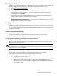
1 HP-UX installation This chapter describes the installation process for the HP Smart Array P700m Controllers on HP-UX servers. Installation overview To install your Smart Array Series Controller, follow these steps: 1. Plan your disk configurations. Supported RAID configurations are 0, 1, 1+0, 5, and ADG. For more information, see the RAID Technology Overview. 2. Check the installation prerequisites. See “Installation prerequisites” (page 4). 3. Check for the latest driver software.
Checking for the latest driver software The drivers, utilities, and manpages for the Smart Array series controllers are located at the HP Software Depot website. To locate and download the software, follow these steps: 1. Go to http://www.software.hp.com. 2. Search for “Smart Array”. 3. Locate the Smart Array P700m bundle and click Receive for Free. 4. Select the HP-UX version that your system runs, complete the required registration information, then click Next. 5.
2. Prepare to run saupdate from the Offline Diagnostics CD or the EFI partition: • To run saupdate from the Offline Diagnostic CD: a. Place the Offline Diagnostic CD containing saupdate.efi in the CD drive before booting the system. b. Boot the system to the EFI Shell prompt. c. Locate the cdrom entry in the list of mapped devices, and change to the device by entering its associated fs number (for example, fs0) under EFI Shell prompt. d.
2. 3. 4. 5. 6. 7. Search for “Smart Array P700m”. In the “Narrow search using only” section, click Drivers and software. Locate and click the link for the firmware download package. Review the installation instructions and release notes on the download page. Download the firmware. Follow the procedures supplied with the update package to install the firmware update. Updating the controller firmware NOTE: The following is a generic procedure to update firmware from the EFI shell.
Percentage completed: 100% Activating firmware now, this may take several minutes. Resetting and reinitializing controller. Retrieving firmware version, this may take several minutes. Current controller firmware version is 6.60 Build 0 Verifying the firmware update To verify that the firmware update was successful, follow these steps: 1. After updating the firmware, cycle the power on the system and on any external JBODS connected to the system. 2.
2. Enter the ioscan -kfnd ciss command: # ioscan -kfnd ciss If the Smart Array Controller software is installed correctly, the generated output looks similar to this: # ioscan -kfnd ciss Class I H/W Path Driver S/W State H/W Type Description ======================================================================= escsi_ctlr 2 0/4/0/0/0/0 ciss CLAIMED INTERFACE PCIe SAS SmartArray P700 RAID Controller /dev/ciss2 If the software is not installed correctly, reinstall it using swinstall.
****************************************************************************** ---- DRIVER INFORMATION -----------------------------------------------------Driver State........................ READY ---- CONTROLLER INFORMATION -------------------------------------------------Controller Product Number........... Controller Product Name............. Hardware Path....................... Serial Number....................... Device File......................... Hardware Revision...................
---- SAS/SATA DEVICE 61:1:30:0x500000e01bbabde3 [DISK] ----------------------Connector Location............................... Connector........................................ Enclosure........................................ Bay.............................................. WWID............................................. Device Type...................................... Disk Capacity.................................... Device Status.................................... Device Vendor ID...................
---- SAS/SATA DEVICE 1E:0:0:0x500508b0001b8edb [SES] ------------------------Connector Location............................... Connector........................................ Enclosure........................................ Bay.............................................. WWID............................................. Device Type...................................... Device Vendor ID................................. Device Product ID................................ Device Serial Number...............
Configuring a Smart Array Series Controller as a boot device This section describes the additional steps you must follow to enable your system to boot from logical drives on a Smart Array Series Controller. NOTE: To create logical drives, use the Option ROM Configuration for Arrays (ORCA) . See “Configuring a logical drive Using ORCA offline” (page 13). For more information, see the HP Smart Array SAS Controllers for Integrity Servers Support Guide .
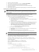
NOTE: Pressing F8 at the ORCA prompt might not start ORCA on all terminals. If ORCA does not start when you press F8, reboot the system and press the key sequence ESC 8 at the ORCA prompt to start ORCA. Figure 1-1 ORCA Main Menu Screen To create a logical drive using ORCA, follow these steps: 1. Select Create Logical Drive. The screen displays a list of available (unconfigured) physical drives and the valid RAID options for the system. 2.
2 OpenVMS installation This chapter describes the installation process for the HP Smart Array P700m Controller on OpenVMS servers. Installation overview To install your Smart Array Series Controller, follow these steps: 1. Plan your disk configurations. For more information, see the RAID Technology Overview. 2. Check the installation prerequisites. See “Installation prerequisites” (page 15) 3. Check for the latest driver software.
Installing software To install Smart Array P700m driver software, follow the procedure in the download package. Connecting external devices The P700m controller is compatible with several HP external storage enclosures. For information on supported enclosures, see the HP Smart Array RAID Controllers Support Matrix. For information on connecting an external enclosure, see the documentation for the enclosure.
******************************************************************************** Smart Array Offline Firmware Update Utility Version 2.09.03.01 (C) Copyright 2009 Hewlett-Packard Development Company, L.P. ******************************************************************************** Seg Bus Dev Func 0 8 0 0 Description Version HP Smart Array P700m External Enclosures Connected : Index Description 0 MDS600 1 MDS600 2 MDS600 3 MDS600 6.60 Build 0 Version 2.48 2.48 2.48 2.
IMPORTANT: Both saupdate.efi and the firmware image file must be located in the same directory. If they are not, copy them both to the EFI partition. Run the saupdate.efi using the fs0:\> saupdate command. • 1. 2. 3. • If you are not using the Offline Diagnostic CD: Download the Smart Array EFI update utility saupdate.efi and copy it to the EFI partition. Download the firmware and copy it to the EFI partition. Boot the system to the EFI Shell and change directories to the EFI partition.
Error messages The following error messages may appear when using the saupdate utility: • When keyword LIST or UPDATE is misspelled or extra parameters are specified: Error: Syntax Error Usage: saupdate LIST or saupdate UPDATE [ | all ] • When the controller ID in the saupdate UPDATE command is not correct: No matching controller found • When a firmware file does not exist in the saupdate UPDATE command, the example shows: INCPTR.BIN does not exist. File INCPTR.
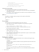
While the ORCA prompt is displayed, press the F8 key to start ORCA. The ORCA main menu is displayed, enabling you to create, view, or delete a logical drive. NOTE: Pressing the F8 key at the ORCA prompt may not start ORCA on all terminals. If ORCA does not start when you press the F8 key, reboot the system and use ESC 8 at the ORCA prompt to start ORCA. Figure 2-1 ORCA Main Menu Screen To create a logical drive using ORCA, follow these steps: 1. Select Create Logical Drive.
3 Hardware installation Card installation varies by server type and model. The following procedures are a general guideline for installing the card. For more information, see your server documentation. WARNING! To reduce the risk of personal injury or damage to the equipment, consult the server documentation safety information. Ensure that you are properly grounded before continuing the installation procedure to not damage electronic components from electrostatic discharge (ESD).
4. Restore the server blade to its operating position in the server blade enclosure. NOTE: By default, the server blade powers on after installation. Installing the cache battery IMPORTANT: The cache battery is required to enable Battery Backed Write Cache for RAID 5 or ADG configurations. NOTE: 1. Plug the battery cable's plug into the cache battery: a.
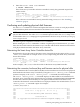
2. Mount the battery on the server blade's battery holder: a. Line up the battery's tabs with the two slots on the battery holder. b. Pull out gently on the battery holder's spring latch, and with the battery closer to the rear of the blade, press down until the tabs go down into the slots. c. Pull out gently on the battery holder's spring latch while sliding the battery back towards the front of the server blade.
The latch fits against one of the tabs on the battery's side to hold the battery in place. 24 3. Push the battery cable down through the battery holder's restraining clip. 4. Plug the battery cable's cache module plug into the cache module's battery connector.
NOTE: down.
5. 7. If the P700m controller is installed in mezzanine slot 3, let the cable lie across the top of the card in slot 2 (if installed) or slot 1 (if installed and no card in slot 2). IMPORTANT: Do not remove the other cards and lay the cable under mezzanine card 1 as this will cause wear on the battery cable's wires, exposed near the cache module plug. In addition, you should route the battery cable so that the cache and battery can be removed together.
4 Support and other resources About this document This document describes how to install HP Smart Array P700m Controllers on HP Integrity servers. Intended audience This document is for system and network administrators responsible for installing, configuring, and managing fault tolerant data storage. Administrators must know operating system concepts, commands, and configuration. Administrators also must know proper electrostatic discharge (ESD) safety procedures for installing the controller hardware.
Include the document title, manufacturing part number, and any comment, error found, or suggestion for improvement you have concerning this document.
A Electrostatic discharge This appendix discusses ways to prevent damage to your system due to Electrostatic Discharge (ESD). Handling parts To prevent damage to your system, you must take precautions when setting up the system or handling parts. A discharge of static electricity from a finger or other conductor can damage system boards or other static-sensitive devices. This type of damage can reduce the life expectancy of the device.