HP Smart Array SAS Controllers for Integrity Servers Support Guide HP-UX 11i v2 and 11i v3 Abstract This document describes how to install, configure, and troubleshoot HP Smart Array SAS controllers on HP Integrity servers running HP-UX.
© Copyright 2011 Hewlett-Packard Development Company L.P Legal Notices The information contained herein is subject to change without notice. The only warranties for HP products and services are set forth in the express warranty statements accompanying such products and services. Nothing herein should be construed as constituting an additional warranty. HP shall not be liable for technical or editorial errors or omissions contained herein.
Contents 1 Controller overview.....................................................................................6 Smart Array P400 controller features...........................................................................................6 Board components and features.............................................................................................6 Smart Array P400 controller board runtime LEDs.................................................................
Configuring a logical drive..................................................................................................46 Deleting a logical drive......................................................................................................48 Clearing the logical drive configuration................................................................................50 Adding a spare disk drive...................................................................................................
Confirming physical disks failures using sautil...........................................................................103 Compromised fault tolerance..................................................................................................104 Recovering from fault tolerance failures...............................................................................104 Physical disk replacement......................................................................................................
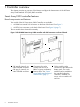
1 Controller overview This chapter provides an overview of the features and physical characteristics of the HP Smart Array Serial-Attached SCSI (SAS) RAID controllers. Smart Array P400 controller features Board components and features Two models of the HP Smart Array P400 Controller are available: • AD348A has internal SAS connectors on the front of the board. See Figure 1. • AD397A has connectors on the back of the board. See Figure 2 (page 7). The two models have identical functionality.
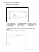
Figure 2 HP AD397A Smart Array P400 controller with SAS connectors on back of board 2 3 1 5 4 6 5 7 4 3 2 1 1 2 Connectors for cache module (also known as BBWC or array accelerator). SAS port 1I (internal), 4x wide SFF8484 connector. 3 4 Runtime LEDs. See “Smart Array P400 controller board runtime LEDs”. SAS port 2I (internal), 4x wide SFF8484 connector. 5 Cache module, with a connector for the cable to the battery pack.
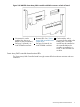
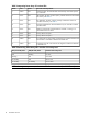
Figure 3 Smart Array P400 controller board runtime LEDs 1 8 Table 1 Interpreting Smart Array P400 Runtime LEDs LED ID Color Name LED name and interpretation 1 Amber CR14 Controller lockup LED. 2 Amber CR13 Disk Failure LED. A physical disk connected to the controller has failed. See the Fault LED on each disk to determine the failed disk. 3 Green CR3 Activity LED for SAS port 2I. 4 Green CR8 Activity LED for SAS port 1I. 5 Green CR5 Command Outstanding LED.
Smart Array P411 controller features Board components and features Figure 4 HP AM311A Smart Array 411 controller components 1 1 2 3 2 Connector for SAS miniports 1 and 2, each 4x wide. Cache module (also known as array accelerator). 3 4 Status LEDs (runtime LEDs). To interpret the illumination pattern of these LEDs, see Table 3 (page 10). 4 (On rear of cache) Connector for the cable to an optional cache battery that upgrades the cache to BBWC.
Table 3 Interpreting Smart Array 411 runtime LEDs LED ID Color Name LED name and interpretation 1 Amber DS9 System Error LED. The controller ASIC has locked up and cannot process any commands. 2 Green DS8 Idle Task LED. This LED, with item 3 (DS7), indicates the amount of controller CPU activity. See Table 6. 3 Green DS7 Gas Pedal LED. This LED, with item 2 (DS8), indicates the amount of controller CPU activity. See Table 4. 4 Green DS6 Controller Heartbeat LED.
Smart Array P700m controller features Board components and features Figure 6 HP 508226-B21 Smart Array P700m controller components 1 2 3 4 1 2 5 Status LEDs (runtime LEDs). To interpret the illumination pattern of these LEDs, see Table 5 (page 12). Connector (not used on HP Integrity servers). 3 4 Cache module (also known as array accelerator). Connector for the cable to an optional cache battery that upgrades the cache to BBWC. This connector is absent on some P700m models.
Table 5 Interpreting Smart Array P700m runtime LEDs LED ID Color Name LED name and interpretation 1 Amber CR10 Thermal Alert LED. This LED is not used. 2 Amber CR9 System Error LED. The controller ASIC has locked up and cannot process any commands. 3 Amber CR1 Diagnostics Error LED. One of the server diagnostics utilities has detected a controller error. 4 Amber CR2 Disk Failure LED. A physical disk connected to the controller has failed.
Smart Array P711m controller features Board components and features Figure 8 HP 513778-B21 Smart Array P711m controller components 1 2 3 1 Mezzanine connector to system board. 2 Status LED (runtime LED). 3 Cache module (also known as array accelerator). The Smart Array P711m Controller also includes an external capacitor pack (not shown), which provides approximately 80 seconds of backup power for the DDR cache memory.
Smart Array P800 controller features Board components and features Figure 10 HP AD335A Smart Array P800 controller components 2 3 4 5 6 7 1 1 2 3 Connector for SAS miniports 1E and 2E (external), each 4x wide. Heartbeat LED (flashes green when operating normally and amber if the controller as failed). Activity LED for external ports. 4 5 SAS port 3I (internal), 4x wide. SAS port 4I (internal), 4x wide. 6 7 Cache module. (Also known as a BBWC or array accelerator.) Batteries for cache module.
Figure 11 Smart Array P800 controller board runtime LEDs 1 10 Table 7 Interpreting Smart Array P800 runtime LEDs LED ID Color Name LED name and interpretation 1 Green CR502 Expander Heartbeat LED. This LED flashes every two seconds during normal operation. Abnormal conditions are indicated as follows: • If the LED glows steadily, the expander has an internal problem. • If the LED flashes twice per second, the NVRAM is corrupt. If an abnormal condition is indicated, the expander does not function.
Smart Array P812 controller features Board components and features Figure 12 HP AM312A Smart Array P812 controller components 1 2 3 4 5 6 1 2 Ports 1E, 2E, 3E, and 4E (Mini SAS 4x connectors). Port 6I (Mini SAS 4i connector). 3 4 Port 5I (Mini SAS 4i connector). Cache module (Also known as array accelerator). 5 7 Capacitor pack for cache module.
Figure 13 Smart Array P812 controller board runtime LEDs 1 9 Table 9 Interpreting Smart Array P812 runtime LEDs LED ID Color Name LED name and interpretation 1 Green CR76 Idle Task LED. This LED, with item 7 (CR504), indicates the amount of controller CPU activity. See Table 10. 2 Green CR75 Gas Pedal LED. This LED, with item 10 (CR503), indicates the amount of controller CPU activity. See Table 10. 3 Green CR74 Controller Heartbeat LED.
Figure 14 Smart Array battery pack LEDs 1 2 3 4 Table 11 Battery pack LEDs LED Color Description 1 Green System Power LED. This LED glows steadily when the system is powered on and 12 V system power is available. This power supply is used to maintain the battery charge and provide supplementary power to the cache microcontroller. 2 Green Auxiliary Power LED. This LED glows steadily when 3.3 V auxiliary voltage is detected.
Table 12 Interpreting battery pack LEDs (continued) LED 3 State LED 4 State Interpretation One flash per second One flash per second An alternating green and amber flash pattern indicates that the cache microcontroller is executing from within its boot loader and receiving new flash code from the host controller. Steady glow -- There is a short circuit across the battery terminals or in the battery pack. BBWC features are disabled until the battery pack is replaced.
controller that failure is imminent. Thus, you can back up data and replace the disk drive before failure occurs. NOTE: An online spare does not become active and start rebuilding when an imminent failure alert is sent, because the degraded disk has not failed yet and is still online. The online spare is activated only after a disk in an array fails. Drive failure alert features Sends an alert message to Event Monitoring Services (EMS) when a physical disk or a logical drive fails.
The rebuilt data is typically written to online spare physical disks. If a second physical disk fails before the data from the initial physical disk failure is rebuilt on the online spare disk, the logical drive fails and data is lost. ADG (RAID 6) An ADG configuration has a minimum of four physical disks, plus one or more online spares. ADG is similar to RAID 5, except that in an ADG configuration the parity data is duplicated on two physical disks instead of one.
Table 15 Supported RAID modes, by controller (continued) Controller 22 RAID 0 RAID 1 RAID 1+0 RAID 5 P800 Yes Yes Yes Yes P812 Yes Yes Yes Yes Controller overview RAID 50 RAID ADG RAID 60 Yes Yes Yes Yes
2 Installing the controller This chapter describes a generic installation process for installing HP Smart Array SAS Controllers on HP-UX servers and updating the drivers and firmware for the storage system components. Procedures and recommendations might differ for individual controller models. Installation guides specific to each controller model are available on the HP website at http://www.hp.com/go/ hpux-iocards-docs. Click the link for your HP-UX version.
Table 16 Minimum Required HP-UX Versions for Smart Array SAS RAID Controllers (continued) Controller Operating System Minimum Required Version Smart Array P411 HP-UX 11i v2 Not supported. HP-UX 11i v3 B.11.31.1005 HP-UX 11i v2 B.11.23.0903 HP-UX 11i v3 B.11.31.0903 HP-UX 11i v2 Not supported. HP-UX 11i v3 B.11.31.1109 HP-UX 11i v2 B.11.23.0712 HP-UX 11i v3 B.11.31.0712 HP-UX 11i v2 Not supported. HP-UX 11i v3 B.11.31.
Installing the controller offline To install a Smart Array controller on a server running HP-UX, follow the procedures in the HP-UX chapter of the installation guide for your controller. Installation guides are available on the HP website at http://www.hp.com/go/hpux-iocards-docs. Click the link for your HP-UX version. Installation guides are listed alphabetically in the “Setup and install — general” section.
3. To replace the controller, follow the procedures in the latest edition of the Interface Card OL* Support Guide for your HP-UX version at http://www.hp.com/go/hpux-core-docs. For instructions on opening the system enclosure and working with PCIe cards, see see the documentation for your server at http://www.hp.com/go/Integrity_Servers-docs. CAUTION: Electronic components can easily be damaged by small amounts of static electricity. To avoid damage, follow the guidelines in Appendix D (page 116). 4.
1. Prepare to run saupdate from the Offline Diagnostics CD or the EFI partition: • To run saupdate from the Offline Diagnostic CD: a. Place the Offline Diagnostic CD containing saupdate.efi in the CD drive before booting the system. b. Boot the system to the EFI Shell prompt. c. Locate the cdrom entry in the list of mapped devices, and change to the device by entering its associated fs number (for example, fs0) under EFI Shell prompt. d.
5. 6. 7. Review the installation instructions and release notes on the download page. Download the firmware. To install the firmware update, follow the procedures supplied with the update package. Updating the controller firmware NOTE: The following is a generic procedure to update firmware from the EFI shell. HP recommends that you follow the procedures supplied with the update package to install the firmware update. To update the firmware image on the controller, use saupdate from the EFI Shell.
2. To update the firmware on the controller, use saupdate UPDATE. The syntax of the saupdate UPDATE command is as follows: saupdate UPDATE For example, to update the controller at segment 0, bus 52, device 0, function 0 from the example output above: fs0:\> saupdate UPDATE 0:52:0:0 INCPTR.PAK Replace INCPTR.PAK with the name of your firmware file. For example: fs0:\EFI\TOOLS> saupdate update 0:52:0:0 INCPTR.
Error messages The following error messages might appear when using saupdate: • When keyword LIST or UPDATE is misspelled or extra parameters are specified: Error: Syntax Error Usage: saupdate LIST or saupdate UPDATE [ | all ] • When the controller ID in the saupdate UPDATE command is not correct: No matching controller found • When a firmware file does not exist in the saupdate UPDATE directory: INCPTR.BIN does not exist. File INCPTR.
2. • To display all detected Smart Array controllers along with the active firmware versions, use saupdate LIST. For example: fs0:\EFI\TOOLS> saupdate list ************************************************************************ Smart Array Offline Firmware Update Utility Version 2.07.09.02 (C) Copyright 2006 Hewlett-Packard Development Company, L.P. Seg 0 Bus 8 Dev 0 Func 0 Description HP Smart Array P800 External Enclosures Connected : Index Description 2 MSA70 Version 4.10 Version 2.
1. Prepare to run saupdate from the Offline Diagnostics CD or the EFI partition: • To run saupdate from the Offline Diagnostic CD: a. Download the firmware and copy it to the EFI partition. b. Place the Offline Diagnostic CD containing saupdate.efi in the CD drive before booting the system. c. Boot the system to the EFI Shell prompt. d. Locate the cdrom entry in the list of mapped devices, and change to the device by entering its associated fs number (for example, fs0) under EFI Shell prompt. e.
2. To confirm that the correct firmware version is installed, use saupdate LIST. See “Verifying the controller firmware” (page 26). For example: fs0:\EFI\TOOLS> saupdate list ************************************************************************ Smart Array Offline Firmware Update Utility Version 2.07.09.02 (C) Copyright 2006 Hewlett-Packard Development Company, L.P.
NOTE: This section of the HP Smart Array Support Guide focuses on the sautil command options used to confirm, or change, physical disk firmware. The other sautil command options listed in the sautil help screen and detailed in the sautil manpages are explained in “The sautil command” (page 60). You must log in as a superuser to run the sautil command.
---- ARRAY ACCELERATOR (CACHE) INFORMATION ----------------------------------Array Accelerator Board Present?.... Cache Configuration Status.......... Cache Ratio......................... Total Cache Size (MB)............... Battery Pack Count.................. Battery Status (pack #1)............
---- SAS/SATA DEVICE 1I:1:10:0x5000c5000032b839 [DISK] ----------------------Connector Location............................... Connector........................................ Enclosure........................................ Bay.............................................. WWID............................................. Device Type...................................... Disk Capacity.................................... Device Status.................................... Device Vendor ID...................
Device Type...................................... Disk Capacity.................................... Device Status.................................... Device Vendor ID................................. Device Product ID................................ Device Serial Number............................. Device Firmware Version.......................... DISK 36.4 GB UNASSIGNED HP DG036A8B53 3LC01ZTE00008524EDPX HPD4 ---- SAS/SATA DEVICE 2I:1:13:0x500000e01118a7a2 [DISK] ----------------------Connector Location.
saconfig utility sees the logical drive as being in use, so configuration changes affecting that drive are not allowed until the drive is no longer the boot device. • When you are not using a logical drive as a boot device, if you clear the controller’s configuration the logical drive is also deleted. If you want a logical drive to remain set up as a boot device, configure a logical drive and then complete the entire boot setup process again.
NOTE: You cannot use ORCA to configure a logical drive using RAID 0; you must use RAID 1+0 or higher. To configure a RAID 0 logical drive online, use the saconfig command. For more information, see “Configuring a logical drive” (page 46). NOTE: You cannot use ORCA to configure a single spare drive to be shared among several arrays. To configure shared spare drives, use the saconfig command. See “Adding a spare disk drive” (page 50). 3. 4. 5. 6. To accept the settings, press Enter.
3 Configuration This chapter explains how to use the saconfig command to configure Smart Array SAS Controllers. NOTE: Command outputs are similar for different Smart Array SAS controllers, so in most cases the example output is shown for only one controller model. If the difference between controllers is significant for a specific command, separate examples from each controller type are provided.
• Set the stripe size on a RAID logical drive • Set up online spare disk drives • Delete logical drives • Clear the current configuration • Specify the percentage of the cache used for read caching • Auto-fail missing disks at boot time • Create multiple logical drives in an array • Perform RAID level migration • Perform stripe size migration • Extend the capacity of a logical drive • Expand the capacity of an array • Change the expand priority • Change the rebuild priority To run
Example 1 The saconfig help screen for HP-UX 11i v3 # saconfig No device file specified ****************************************************************************** ****************************************************************************** **** **** **** S A C O N F I G U t i l i t y **** **** **** **** for the HP SmartArray RAID Controller Family **** **** **** **** version A.01.20 **** **** **** **** (C) Copyright 2003-2007 Hewlett-Packard Development Company, L.P.
saconfig /dev/cissX -e To change the rebuild priority of controller to low, medium, or high saconfig /dev/cissX -r To specify the percentage of total cache size to be used for read caching saconfig /dev/cissX -C Read caching percentage can be 0, 25, 50, 75, or 100.
Example 2 The saconfig help screen for HP-UX 11i v2 # saconfig No device file specified ****************************************************************************** **** **** **** S A C O N F I G U t i l i t y **** **** **** **** for the HP SmartArray RAID Controller Family **** **** **** **** version A.01.18 **** **** **** **** (C) Copyright 2003-2006 Hewlett-Packard Development Company, L.P.
Read caching percentage can be 0, 25, 50, 75, or 100. To enable or disable auto-fail missing disks at boot saconfig /dev/cissX -F on|off To identify (light LED) SAS/SATA physical drives saconfig /dev/cissX -I -p [-p ... ] To identify SAS/SATA physical drives constituting a logical drive saconfig /dev/cissX -I -l To extend the capacity of the specified logical drive up to larger capacity. The capacity is in GB.
Internal 2I 1 13 0x500000e01118a7a2 36.
saconfig command, as described in “Displaying the Smart Array controller configuration” (page 45). [-s ] Configures a physical disk as a spare. The physical disk is identified by Connector/Enclosure/Bay or WWID. Obtain this information from the output of the saconfig command, as described in “Displaying the Smart Array controller configuration” (page 45). [-c ] Specifies the size in GB of the logical drive to be created.
Deleting a logical drive To delete a logical drive that has been configured on a Smart Array Controller, use the command saconfig /dev/cissX -D .
Example 3 Using saconfig to determine logical drive numbers # saconfig /dev/ciss4 ---------- LOGICAL DRIVE 0 Device File RAID Level Size Stripe Size Status = = = = = 1 ---------- c4t0d0 0 20479 MB 128 KB OK Participating Physical Drive(s): Ct 1E Enc 1 Bay 9 WWID 0x500000e015141982 2 Participating Spare Drive(s): None ---------- LOGICAL DRIVE 1 ---------Device File RAID Level Size Stripe Size Status = = = = = c4t0d1 0 20479 MB 128 KB OK Participating Physical Drive(s): Ct 1E Enc 1 Bay 9 WWID
# saconfig /dev/ciss4 -D 0 Deleting logical drive 0 will cause gap saconfig (/dev/ciss4): Current driver state is READY # saconfig /dev/ciss4 -D 1 Deleting logical drive 1 will cause gap between logical drives 0 and 2 saconfig (/dev/ciss4): Current driver state is READY Example 4 Deleting multiple logical drives in reverse drive number order # saconfig /dev/ciss4 -D 2 Are you sure you want to delete logical drive 2 on SmartArray RAID controller /dev/ciss4? (y/[n]): y Logical drive 2 deleted # saconfig /dev
Changing the rebuild priority of a logical drive To set the rebuild priority of logical drives, use the saconfig /dev/cissX -r command. For example: # saconfig /dev/ciss5 -r high In this example, the rebuild priority is set to high for the logical drives under controller ciss5. Specifying the percentage of cache used for read caching To specify a percentage of cache to be used exclusively for read caching, use the saconfig /dev/cissX -C command.
Performing stripe size migration To perform a migration of a logical drive to a different stripe size, use the command: saconfig /dev/cissX -M -S For example: # saconfig /dev/ciss5 -M 0 -S 64 Logical drive 0 migrated from stripe 16 to 64 KB Extending the capacity of a logical drive WARNING! The logical drive capacity specified with option c must be larger than the existing capacity, or data loss occurs.
Using ORCA HP Smart Array controllers include ORCA, a menu-driven, ROM-based offline configuration utility. You can use ORCA to create, view, and delete logical drives before loading an operating system. To access ORCA, follow the procedures in the installation guide for your controller. Installation guides are available on the HP website at: http://www.hp.com/go/hpux-iocards-docs Click the link for your HP-UX version.
6. To save the configuration, press F8. A confirmation screen appears: 7. To acknowledge that the configuration was saved and return to the ORCA Main Menu, press Enter. Deleting a logical drive WARNING! Back up all necessary data before deleting the logical drive. When you delete a logical drive, data on the drive is not preserved. To delete a logical drive using ORCA: 1. From the Main Menu, select “Delete Logical Drive.” A screen similar to the following appears: 2.
3. To delete the logical drive, press F8. A warning and confirmation screen appears: 4. After you carefully review your selection, press F3 to delete the logical drive. A confirmation screen appears. 5. To acknowledge that the configuration was saved and return to the ORCA Main Menu, press Enter. Moving disks and arrays to different positions or controllers You can move disks and arrays to different positions or controllers.
1. 2. Review the documentation for the volume manager or other product that is managing the disks you are moving. The volume manager or other product might have additional prerequisites or procedures that you must follow. • For LVM or Veritas Volume Manager (VxVM) documentation, see the documents at www.hp.com/go/hpux-core-docs. • For other products, see the documentation provided by the manufacturer.
8. Check /var/adm/syslog/syslog.log for the following messages: CISS: RAID SA controller on hardware path has detected the removal of a physical disk CISS: RAID SA controller on hardware path has detected the insertion of a physical disk IMPORTANT: If these messages are not present, the disk movement was not successful. Power off the system and return the disks to their original locations. You might need to restore the data from backup media. 9.
11. If you did not power off the destination system, use the sautil reset_ctlr command to make the new disks or array visible on the server. See “The sautil command” (page 60). 12. To verify the new disk configuration, use ORCA or sautil. See “Using ORCA” (page 53) and “The sautil command” (page 63).
4 Troubleshooting This chapter describes diagnostic and troubleshooting tools for Smart Array Series Controllers. NOTE: Command outputs are similar for different Smart Array SAS controllers, so in most cases the example output is shown for only one controller model. If the difference between controllers is significant for a specific command, separate examples from each controller type are provided.
NOTE: PCI Error Recovery is not supported on all platforms. To determine if PCI Error Recovery is supported on your system, see the PCI Error Recovery Support Matrix at http://www.hp.com/ go/hpux-iocards-docs. With the PCI Error Recovery feature enabled, if an error occurs on a PCI bus containing an I/O card that supports PCI Error Recovery, the following events occur: • The PCI bus is quarantined to isolate the system from I/O and to prevent the error from damaging the system.
Example 5 The sautil help screen # sautil ****************************************************************************** **** **** **** S A U T I L S u p p o r t U t i l i t y **** **** **** **** for the HP SmartArray RAID Controller Family **** **** **** **** version A.02.13 **** **** **** **** (C) Copyright 2003-2007 Hewlett-Packard Development Company, L.P.
This command option is described in “Using sautil to check and update the controller firmware” (page 78). To update physical disk firmware, use the following command: # sautil download_dev_fw This command option is described in “Confirming and updating physical disk firmware” (page 33).
The sautil command To view detailed information on the HP Smart Array controller, configured logical drives, and devices attached to the controller, use the sautil command output. The-s option provides a shorter and less detailed output. For an example of the sautil -s command output, see “Confirming and updating physical disk firmware” (page 33). NOTE: For troubleshooting, use the sautil command.
Example 6 Typical sautil command output # sautil /dev/ciss3 ****************************************************************************** **** **** **** S A U T I L S u p p o r t U t i l i t y **** **** **** **** for the HP SmartArray RAID Controller Family **** **** **** **** version A.02.13 **** **** **** **** (C) Copyright 2003-2007 Hewlett-Packard Development Company, L.P.
internal internal internal external external external external external external external external external external external external internal 3I 3I 3I 2E 2E 2E 2E 2E 1E 1E 1E 1E 1E 1E 2E 1 1 1 1 1 1 1 1 1 1 1 1 1 1 1 0 3 2 1 1 2 3 4 5 1 2 3 4 5 0 0 0 0x5000c500014b62a1 0x5000c500014aca69 0x5000c500014b6145 0x5000c50005962f7d 0x5000c50005962a09 0x5000c50005961095 0x5000c500052d0589 0x5000c500052d7595 0x5000c500052d45f9 0x5000c500052d6989 0x5000c500052d6335 0x5000c500052d5175 0x5000c500052d636d 0x50001c
Logical Drive Cache Status.......... cache enabled Configuration Signature............. 0xA0008383 Media Exchange Detected?............ no ---- LOGICAL DRIVE 2 --------------------------------------------------------Logical Drive Device File........... Fault Tolerance Mode................ Logical Drive Size.................. Logical Drive Status................ # of Participating Physical Disks... c3t0d2 RAID 0 (no fault tolerance) 10239 MB OK 1 Participating Physical Disk(s)......
Enclosure........................................ Bay.............................................. WWID............................................. Device Type...................................... Disk Capacity.................................... Device Status.................................... Device Vendor ID................................. Device Product ID................................ Device Serial Number............................. Device Firmware Version..........................
---- SAS/SATA DEVICE 3I:1:2:0x5000c500014aca69 [DISK] -----------------------Connector Location............................... Connector........................................ Enclosure........................................ Bay.............................................. WWID............................................. Device Type...................................... Disk Capacity.................................... Device Status.................................... Device Vendor ID...................
Supports redundant controller operation........ no Disk write cache enabled in current page....... no Disk write cache disabled in default page...... yes ---- SAS/SATA DEVICE 2E:1:1:0x5000c50005962f7d [DISK] -----------------------Connector Location............................... Connector........................................ Enclosure........................................ Bay.............................................. WWID............................................. Device Type...................
S.M.A.R.T. enabled............................. S.M.A.R.T. errors (in powerup M&P data)........ Attached to external connector................. Configured in a logical drive.................. Configured as a spare disk..................... Disk write cache enabled at spin up............ yes no yes yes no no Supports redundant controller operation........ no Disk write cache enabled in current page....... no Disk write cache disabled in default page......
Physical Disk Flags: Disk present and operational................... yes Non-disk device detected....................... no S.M.A.R.T. supported........................... S.M.A.R.T. errors (in factory M&P data)........ S.M.A.R.T. enabled............................. S.M.A.R.T. errors (in powerup M&P data)........ Attached to external connector................. Configured in a logical drive.................. Configured as a spare disk..................... Disk write cache enabled at spin up............
Device Firmware Version.......................... Reserved Area (cfg/status info).................. Block Size (bytes/sector)........................ M&P Data Stamped?................................ Last Failure Reason.............................. HPD2 33554.4 KB (33.6 MB) 512 bytes yes INIT REQUEST SENSE FAILED Physical Disk Flags: Disk present and operational................... yes Non-disk device detected....................... no S.M.A.R.T. supported........................... S.M.A.R.T.
Device Type...................................... Disk Capacity.................................... Device Status.................................... Device Vendor ID................................. Device Product ID................................ Device Serial Number............................. Device Firmware Version.......................... Reserved Area (cfg/status info).................. Block Size (bytes/sector)........................ M&P Data Stamped?................................
Connector Location............................... Connector........................................ Enclosure........................................ Bay.............................................. WWID............................................. Device Type...................................... Disk Capacity.................................... Device Status.................................... Device Vendor ID................................. Device Product ID................................
Disk write cache disabled in default page...... no ---- SAS/SATA DEVICE :0:0:0x500110a0004af23e [SES] --------------------------Connector Location............................... Connector........................................ Enclosure........................................ Bay.............................................. WWID............................................. Device Type...................................... Disk Capacity.................................... Device Status....................
USING INTERIM RECOVERY MODE • An array expansion was aborted. • The logical drive is temporarily disabled because another logical drive on the controller had a missing disk at power on. Also known as a “degraded” state. A physical disk in a fault tolerant logical drive has failed. For RAID 1, 1+0 or 5, data loss can result if a second disk fails. For RAID ADG, data loss can result if two additional disks fail.
The sautil scan command To instruct the Smart Array Controller to rescan all SCSI buses, use the sautil scan command. For example, when you hot-plug a physical disk into the system’s internal drive bay, run a scan. The sautil accept_media_xchg command You can use the sautil accept_media_xchg command to instruct the Smart Array Controller to do the following: 1.
The sautil set_transfer_rate command To set the Smart Array Controller SCSI transfer rate to a lower speed than the controller normally allows, use the sautil set_transfer_rate command.
**** S A U T I L S u p p o r t U t i l i t y **** **** **** **** for the HP SmartArray RAID Controller Family **** **** **** **** version A.02.11 **** **** **** **** (C) Copyright 2003-2006 Hewlett-Packard Development Company, L.P. **** ****************************************************************************** ---- DRIVER INFORMATION -----------------------------------------------------Driver State........................
---- DRIVER INFORMATION -----------------------------------------------------Driver State........................ READY ---- CONTROLLER INFORMATION -------------------------------------------------Controller Product Number........... Controller Product Name............. Hardware Path....................... Device File.........................
Connector:Enclosure:Bay or WWID for each physical disk connected to the Smart Array Controller from the SAS/SATA DEVICE SUMMARY in the output of the sautil command, or from the sautil -s command. When you enter the following command, sautil download_dev_fw the installed physical disk firmware version is listed with the firmware version in .
****************************************************************************** **** End of SAUTIL Output **** ****************************************************************************** In this example, the physical disk (1I:1:9 or 0x5000c5000030b0c5) firmware is updated from HPD3 to HPD4. NOTE: Repeat this procedure for each physical disk where you want to update the firmware.
Hardware Path....................... Serial Number....................... Device File......................... Hardware Revision................... Firmware Revision (in ROM).......... # of Logical Drives................. # of Physical Disks Configured...... # of Physical Disks Detected........ 0/6/0/0/0/0/1/0/0/0 P98690D9SU40R7 /dev/ciss3 'D' 4.10 10 54 58 ---- ARRAY ACCELERATOR (CACHE) INFORMATION ----------------------------------Array Accelerator Board Present?.... Cache Configuration Status..........
external external external external external external external external external external external external external external external external external external external external external external external external external external external external external internal 2E 2E 1E 1E 1E 1E 1E 1E 1E 1E 1E 1E 1E 1E 1E 1E 1E 1E 1E 1E 1E 1E 1E 1E 1E 1E 1E 1E 2E 1 1 1 1 1 1 1 1 1 1 1 1 1 1 1 1 1 1 1 1 1 1 1 1 1 1 1 1 1 0 24 25 1 2 3 4 5 6 7 8 9 10 11 12 13 14 15 16 17 18 19 20 21 22 23 24 25 0 0 0 0x5000c500014
---- SAS/SATA DEVICE 4I:1:6:0x500000e015b2f352 [DISK] -----------------------Connector Location............................... Connector........................................ Enclosure........................................ Bay.............................................. WWID............................................. Device Type...................................... Disk Capacity.................................... Device Status.................................... Device Vendor ID...................
WWID............................................. Device Type...................................... Disk Capacity.................................... Device Status.................................... Device Vendor ID................................. Device Product ID................................ Device Serial Number............................. Device Firmware Version.......................... 0x5000c500014aca69 DISK 73.
---- SAS/SATA DEVICE 2E:1:4:0x5000c500052d0589 [DISK] -----------------------Connector Location............................... Connector........................................ Enclosure........................................ Bay.............................................. WWID............................................. Device Type...................................... Disk Capacity.................................... Device Status.................................... Device Vendor ID...................
WWID............................................. Device Type...................................... Disk Capacity.................................... Device Status.................................... Device Vendor ID................................. Device Product ID................................ Device Serial Number............................. Device Firmware Version.......................... 0x5000c500052d2991 DISK 73.
---- SAS/SATA DEVICE 2E:1:13:0x5000c5000594e865 [DISK] ----------------------Connector Location............................... Connector........................................ Enclosure........................................ Bay.............................................. WWID............................................. Device Type...................................... Disk Capacity.................................... Device Status.................................... Device Vendor ID...................
WWID............................................. Device Type...................................... Disk Capacity.................................... Device Status.................................... Device Vendor ID................................. Device Product ID................................ Device Serial Number............................. Device Firmware Version.......................... 0x5000c5000595ec55 DISK 73.
---- SAS/SATA DEVICE 2E:1:22:0x5000c5000149f175 [DISK] ----------------------Connector Location............................... Connector........................................ Enclosure........................................ Bay.............................................. WWID............................................. Device Type...................................... Disk Capacity.................................... Device Status.................................... Device Vendor ID...................
WWID............................................. Device Type...................................... Disk Capacity.................................... Device Status.................................... Device Vendor ID................................. Device Product ID................................ Device Serial Number............................. Device Firmware Version.......................... 0x5000c500052d45f9 DISK 73.
---- SAS/SATA DEVICE 1E:1:6:0x5000c500052e9b81 [DISK] -----------------------Connector Location............................... Connector........................................ Enclosure........................................ Bay.............................................. WWID............................................. Device Type...................................... Disk Capacity.................................... Device Status.................................... Device Vendor ID...................
WWID............................................. Device Type...................................... Disk Capacity.................................... Device Status.................................... Device Vendor ID................................. Device Product ID................................ Device Serial Number............................. Device Firmware Version.......................... 0x5000c500052d619d DISK 73.
---- SAS/SATA DEVICE 1E:1:15:0x5000c50005962f95 [DISK] ----------------------Connector Location............................... Connector........................................ Enclosure........................................ Bay.............................................. WWID............................................. Device Type...................................... Disk Capacity.................................... Device Status.................................... Device Vendor ID...................
WWID............................................. Device Type...................................... Disk Capacity.................................... Device Status.................................... Device Vendor ID................................. Device Product ID................................ Device Serial Number............................. Device Firmware Version.......................... 0x5000c500014527c1 DISK 73.
---- SAS/SATA DEVICE 1E:1:24:0x5000c50001452b7d [DISK] ----------------------Connector Location............................... Connector........................................ Enclosure........................................ Bay.............................................. WWID............................................. Device Type...................................... Disk Capacity.................................... Device Status.................................... Device Vendor ID...................
WWID............................................. Device Type...................................... Disk Capacity.................................... Device Status.................................... Device Vendor ID................................. Device Product ID................................ Device Serial Number............................. Device Firmware Version.......................... 0x500110a0004af23e SES 0.0 GB FAILED HP P800 P98690D9SU40R7 1.
---- DRIVER INFORMATION -----------------------------------------------------Driver State........................ READY ---- CONTROLLER INFORMATION -------------------------------------------------Controller Product Number........... Controller Product Name............. Hardware Path....................... Device File.........................
5 Support and other resources About this document This document describes how to configure and troubleshoot HP Smart Array SAS Controllers in HP Integrity servers. Intended audience This document is for system and network administrators responsible for installing, configuring, and managing fault tolerant data storage. Administrators must know operating system concepts, commands, and configuration.
Include the document title, manufacturing part number, and any comment, error found, or suggestion for improvement you have concerning this document.
A Physical disk installation and replacement This appendix discusses the procedure for replacing physical disks in an array. Overview When a physical disk fails, the logical drive it belongs to is affected. Each logical drive connected to a Smart Array Controller can be configured with a different RAID level. Logical drives can be affected differently by a physical disk failure, depending on their configured RAID level.
Table 18 SAS physical disk LED illumination patterns Fault/ID LED (1) Online LED (2) Amber/Blue Green Interpretation Alternating amber and blue On, off, or flashing The disk has failed, or a predictive failure alert has been received for this disk; it also has been selected by a management application. Steady blue On, off, or flashing The disk is operating normally and it has been selected by a management application.
For example, in the following sautil command output excerpt, spare disk 1I:1:10 is being substituted for failed disk 1I:1:11, which is why the logical drive is in the RECOVERING state.
3. 4. 5. 6. Replace failed disks. After the failed disks are replaced, if fault tolerance is compromised, power the disk enclosure off and back on again. If you were not able to recover your data using the power-cycling procedure, you must restore your data from backup media. Run the sautil accept_media_xchg command on the affected logical drive. This restores the logical drive’s configuration. Restore your data from backup media.
To minimize the likelihood of fatal system errors, take these precautions when removing failed disks: • • • Do not remove a degraded disk if another disk in the array is offline (the Online/Activity LED is off). In this situation, no other disk in the array can be removed without data loss. The following cases are exceptions: • When RAID 1+0 is used, disks are mirrored in pairs.
• Availability of drive cache. • Brand, model, and age of the disks. • Amount of unused capacity on the disks. • Number of disks in the array (for RAID 5 and RAID ADG). System performance is affected during the rebuild, and the system is unprotected against further disk failure until the rebuild has finished. Therefore, replace disks during periods of low activity when possible.
1. 2. Shut down and power off the server. Remove the replacement physical disk (the one undergoing a rebuild), and reinstall the disk that is being replaced. 3. Power on the server. If the newly failed disk seems to be operational again: 1. Back up unsaved data. 2. Remove the disk that was to be replaced, and reinstall the replacement disk. The rebuild process restarts. 3. When the rebuild process finishes, replace the newly failed disk. If the newly failed disk has not become operational: 1.
B Logical drive failure probability This appendix discusses the probability of logical drive failure. RAID level and probability of drive failure The probability that a logical drive will fail depends on the RAID level setting. • A RAID 0 logical drive fails if only one physical disk fails.
Figure 17 Relative probability of logical drive failure 110 Logical drive failure probability
C Power-on Self Test (POST) error codes This appendix lists the error codes that can be returned by HP Smart Array Controller Option ROM during Power-On Self Test (POST), and provides details of corrective actions you can take. POST error codes The Smart Array Controller provides diagnostic error messages to the server BIOS at reboot. Many of these POST messages are self-explanatory and suggest corrective actions for troubleshooting. Detailed information and corrective actions are listed in Table 20.
Table 20 Smart Array controller POST error codes (continued) Error code Description Level Corrective action 1729 Slot z Drive Array – Disk Performance Optimization Scan in Progress RAID 4/5/ADG performance may be higher after completion. None None. 1764 Slot z Drive Array - Capacity Expansion Process is Temporarily Disabled (followed by one of the following): Informational or No F1 prompt if disable reason is None “rebuild running.
Table 20 Smart Array controller POST error codes (continued) Error code 1783 Description Slot z Drive Array Controller Failure (might be followed by an exclamation point, and one or more of the following:) Level Critical Corrective action Contact your HP support representative for assistance.
Table 20 Smart Array controller POST error codes (continued) Error code 1786 Description Slot z Drive Array Recovery Needed. Level Corrective action Informational Follow the instructions in the error message to correct the error condition. Informational Replace the indicated disk. Informational Press F1 to continue. The drive array remains disabled. The following disk drive(s) need Automatic Data Recovery (Rebuild): Port 1I: Box 2: Bay 5 Select "F1" to continue with recovery of data to drive(s).
Table 20 Smart Array controller POST error codes (continued) Error code 1795 Description Slot z Drive Array - Array Accelerator Configuration Error. Data does not correspond to this drive array Level Corrective action Critical Check the array configuration. Critical Check the cache module, and replace if necessary. Critical The cache module has failed. Contact your HP service representative for assistance. Critical Array Accelerator is disabled. The cache module has failed.
D Electrostatic discharge This appendix discusses how to prevent damage to your server due to Electrostatic Discharge (ESD). Handling parts To prevent damage to your server, you must take precautions when setting up the server or handling parts. A discharge of static electricity from a finger or other conductor can damage system boards or other static-sensitive devices. This type of damage can reduce the life expectancy of the device.
E Cable kits This appendix provides details on the internal and external cable kits available for HP Smart Array SAS controllers. Table 21 Internal SAS cable kits Description Part Number Multilane A cable 389647-B21 Host fan cable 389650-B21 Target fan cable 389653-B21 Multilane B cable 389659-B21 Multilane 76-cm (30-in) cable 389662-B21 Multilane 48-cm (19-in) cable 391330-B21 Table 22 External SAS cable kits Type of Cable Length Part Number External SAS 1.0 m (3.
F Controller specifications This appendix provides specification details for HP Smart Array SAS Controllers. Table 23 Smart Array P400 controller specifications Dimensions (excluding bracket) 16.8 cm x 7.0 cm x 1.8 cm (6.61 in x 2.75 in x 0.
Table 24 Smart Array P411 controller specifications (continued) NOTE: Support for greater than 2TB in a single logical drive.
Table 26 Smart Array P711m controller specifications (continued) Maximum number of physical drives (using all four ports) 108 external Maximum number of logical drives 512 external Memory bus speed DDR2-800 (6.4 GiB/s maximum bandwidth) Number of SAS ports Four (4) 2x connectors external SAS port link rate 6Gb/s per physical link Disk drive and enclosure protocol support SAS protocol: 6 Gb/s, 3 Gb/s, or 1.5 Gb/s SATA protocol: 3 Gb/s or 1.
Table 28 Smart Array P812 controller specifications Dimensions (excluding bracket) Full-height, full-length PCI Express 12.3 in x 4.4 in x 0.5 in (31.1 cm x 11.1 cm x 1.2 cm) PCI label PCIe2 x8 (i.e., x8 mechanical, up to x8 electrical) PCI link rate x8 5 GT/s PCI Express (4 GB/s maximum bandwidth in each direction) SAS/SATA connectivity 2 Mini SAS 4i connectors 4 Mini SAS 4x connectors SAS/SATA link rate SAS protocol: 6 Gb/s, 3 Gb/s, or 1.5 Gb/s SATA protocol: 3 Gb/s or 1.
G Regulatory compliance notices Federal Communications Commission notice Part 15 of the Federal Communications Commission (FCC) Rules and Regulations has established Radio Frequency (RF) emission limits to provide an interference-free radio frequency spectrum. Many electronic devices, including computers, generate RF energy incidental to their intended function and are, therefore, covered by these rules.
For questions regarding this product, contact us by mail or telephone: • Hewlett-Packard Company P. O. Box 692000, Mail Stop 530113 Houston, Texas 77269-2000 • 1-800-HP-INVENT (1-800-474-6836). (For continuous quality improvement, calls may be recorded or monitored.) For questions regarding this FCC declaration, contact us by mail or telephone: • Hewlett-Packard Company P. O.
This marking is valid for non-Telecom products and EU harmonized Telecom products (e.g. Bluetooth). This marking is valid for EU non-harmonized Telecom products.
Class B equipment Battery replacement notice This component uses a nickel metal hydride (NiMH) battery pack. WARNING! There is a risk of explosion, fire, or personal injury if a battery pack is mishandled. To reduce this risk: • Do not attempt to recharge the batteries if they are disconnected from the controller. • Do not expose the battery pack to water, or to temperatures higher than 60°C (140°F). • Do not abuse, disassemble, crush, or puncture the battery pack.
H Frequently asked questions H.1 How many Smart Array Controllers can I install in my server? The maximum number of controllers is restricted to the number of PCIe slots not used for other peripherals. The power rating of the server also limits the number of controllers. For example, each Smart Array P400 Controller requires 14 W, and each Smart Array P800 Controller requires 25 W. The server must be capable of supplying adequate power to each controller.
see “The sautil accept_media_xchg command” (page 77). If auto-fail is disabled in the previous scenario, select one of the following options when the Smart Array POST error is displayed: 1. Power off the server and reconnect the disks, and then power on the server. 2. Press F1. The controller temporarily disables all logical drives, including the intact boot volume. The server fails to boot. 3. Press F2.
I Acronyms used in this document 128 ADG Advanced Data Guarding ARM Auto Reliability Monitoring ASIC Application-Specific Integrated Circuit BBWC Battery-Backed Write Cache BIOS Basic Input-Output System CISS Compaq Intelligent Storage System CPU Command Processing Unit CRA Critical Resource Analysis EFI Extensible Firmware Interface EMS Event Monitoring System ESD Electro-Static Discharge FBWC Flash-Backed Write Cache HPMC High Priority Machine Check I/O Input/Output JBOD Jus
Glossary array A set of physical disks configured into logical drives. Arrayed disks have significant performance and data protection advantages over nonarrayed disks. array accelerator A component of some Smart Array Series controllers that dramatically improves disk read and write performance by providing a buffer. Data integrity is protected by a backup battery and ECC memory. array capacity expansion See capacity expansion.
logical drive capacity extension See capacity extension. online spare A disk in a fault-tolerant system that normally contains no data. When another disk in the array fails, the controller rebuilds the data that was on the failed disk to the online spare. Also known as a hot spare. PCIe An enhanced PCI bus that enables operation at 266 MHz, equivalent to a data throughput of 2.5 GB/s. rebuild See Automatic Data Recovery. Redundant Array of Independent Disks (RAID) A form of fault tolerance.