HP Smart Array P800 Controller for Integrity Servers User Guide October 2006 (Second Edition) Part Number 432599-002
© Copyright 2006 Hewlett-Packard Development Company, L.P. The information contained herein is subject to change without notice. The only warranties for HP products and services are set forth in the express warranty statements accompanying such products and services. Nothing herein should be construed as constituting an additional warranty. HP shall not be liable for technical or editorial errors or omissions contained herein. Microsoft and Windows are U.S. registered trademarks of Microsoft Corporation.
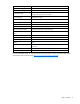
Contents Hardware features ........................................................................................................................ 5 Main components on the board .................................................................................................................. 5 Controller specifications ............................................................................................................................. 5 Overview of the installation procedure .....................
Diagnostic tools ...................................................................................................................................... 36 Electrostatic discharge ................................................................................................................. 37 Preventing electrostatic discharge .............................................................................................................. 37 Grounding methods to prevent electrostatic discharge .............
Hardware features In this section Main components on the board ................................................................................................................. 5 Controller specifications ............................................................................................................................
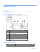
Dimensions (excluding bracket) 31.1 cm × 11.1 cm × 1.2 cm (12.3 in × 4.4 in × 0.5 in) Type of drives supported 3 Gb/s SAS or 1.
Overview of the installation procedure In this section Quick installation procedure (Windows or Linux) ......................................................................................... 7 Quick installation procedure (Windows or Linux) Before installing the controller, refer to the support matrix on the HP website (http://www.hp.com/products1/serverconnectivity) to confirm that the server and operating system support the controller. To install the controller: 1. Power down the server. 2.
The latest firmware, drivers, utilities, software, and documentation for HP Integrity servers are available on the support page of the HP website (http://www.hp.com/support/itaniumservers).
Installing the controller hardware In this section Before beginning the installation ................................................................................................................ 9 Preparing the server ................................................................................................................................. 9 Installing the controller board ....................................................................................................................
3. Remove the slot cover. Save the retaining screw, if one is present. 4. Slide the controller board along the slot alignment guide, if one is present, and press the board firmly into the slot so that the contacts on the board edge are properly seated in the system board connector. 5. Secure the controller board in place with the retaining screw. If the slot alignment guide has a latch (near the rear of the board), close the latch. 6. Connect storage devices to the controller.
c. Release the tab. 3. Connect the other end of the cable to the SAS input connector of the external storage enclosure. • If the enclosure uses a standard SAS 4x connector, insert the cable connector into the enclosure connector, and then tighten the lock screws on the cable connector. • If the enclosure uses a mini SAS 4x connector, pull back the tab on the cable connector, insert the cable connector into the enclosure connector, and then release the tab. 4. Power up the enclosure. 5.
Updating the firmware In this section Methods for updating the firmware (Windows® or Linux®)......................................................................... 12 Methods for updating the firmware (Windows® or Linux®) To update the firmware on the server, controller, or hard drives, use Smart Components. The most recent version of a particular component is available on the support page of the HP website (http://www.hp.com/support). Some components are also available on the Smart Setup media. 1.
Configuring an array In this section Utilities available for configuring an array................................................................................................. 13 Comparing the utilities ............................................................................................................................ 13 Using ORCA.......................................................................................................................................... 14 Using ACU ................
Supported procedures ACU ORCA Creation and deletion of arrays and logical drives + + Assignment of RAID level + + Sharing of spare drives among several arrays + -- Assignment of multiple spare drives per array + -- Setting of stripe size + -- Migration of RAID level or stripe size + -- Configuration of controller settings + -- Expansion of an array + -- Creation of multiple logical drives per array + -- Using ORCA 1. Power up the server.
NOTE: Newly created logical drives are invisible to the operating system. To make the new logical drives available for data storage, format them using the instructions given in the operating system documentation. Using ACU For detailed information about using ACU, see the Configuring Arrays on HP Smart Array Controllers Reference Guide. This document is available on the Smart Setup media or the Documentation CD that is provided in the controller kit.
Installing device drivers and Management Agents In this section Systems using Microsoft® Windows® ...................................................................................................... 16 Systems using Linux®..............................................................................................................................
2. Reboot the server. 3. Follow the standard procedure for installing Linux. As Linux is installed, it recognizes the controller and automatically loads the correct driver. In a system that already has Linux installed: 1. Power down the system. 2. Follow the standard controller installation procedure. 3. Power up the system. As Linux boots, it recognizes the controller. 4.
Upgrading or replacing controller options In this section Replacing or adding a battery ................................................................................................................. 18 Replacing the cache module or controller.................................................................................................. 22 Replacing or adding a battery CAUTION: Electrostatic discharge can damage electronic components. Be sure you are properly grounded before beginning this procedure.
6. While holding the battery assembly, tilt the clip until it is at about 30 degrees to the batteries, and then push the clip in line with the clip hinges until the clip detaches from the batteries. The rest of the procedure depends on whether you are replacing a battery or adding one. 7. • If you are replacing a battery, continue with the next step. • If you are only adding an optional third battery, go to step 9. Separate the batteries. a. Turn the batteries over. b.
9. Position the new battery and the remaining good battery as indicated, and then push them together and slide them until they are aligned. The batteries combine into one unit. 10. Install the battery clip. a. Position the clip so that the hinges on the clip are next to the appropriate hinge pillars on the batteries. b. Hold the clip at about 30 degrees to the batteries. c. Push the clip at the hinges until the clip clicks into place. 11. Reinstall the batteries. a.
b. Position the batteries so that the pegs A on the underside of each battery are in the appropriate holes B on the controller board and pegs C are in slots D. c. Slide the batteries toward the board bracket until they are firmly seated against the connectors on the cache module. 12. Secure the battery clip to the controller board: a. Swivel the clip over the cache module (1).
b. Push the clip firmly at both ends (2) until it clicks into place under the controller board. 13. Reinstall the controller in the server. After installing a battery pack, you might see a POST message during reboot indicating that the array accelerator (cache) is temporarily disabled. This behavior is normal because the new battery pack is likely to have a low charge. You do not need to take any action because the recharge process begins automatically when the battery pack is installed.
4. Pull the flanges on the battery clip outward (1), and then swivel the clip 180 degrees so that it rests on the batteries (2). 5. Swivel the latches on the DIMM connector outward (1). 6. Slide the battery assembly and the cache module off the controller board (2). The procedure at this point depends on whether you are replacing the controller or the cache module. 7. • If you are replacing the controller, go directly to the next step.
b. Position the batteries so that the pegs A on the underside of each battery are in the appropriate holes B on the controller board and pegs C are in slots D. c. Slide the batteries toward the board bracket until the connectors on the cache module are firmly seated in the DIMM connector. (When the cache module is correctly seated, the gold contacts on the cache module are completely hidden within the DIMM connector.) 8. Secure the battery clip to the controller board. a.
b. Push the clip firmly at both ends (2) until it clicks into place under the controller board. 9. Reinstall the controller in the server.
Replacing, moving, or adding hard drives In this section Identifying the status of a hard drive ......................................................................................................... 26 Recognizing hard drive failure................................................................................................................. 27 Replacing hard drives .............................................................................................................................
Online/activity LED Fault/UID LED (green) (amber/blue) Interpretation Flashing regularly (1 Hz) Do not remove the drive. Removing a drive may terminate the current operation and cause data loss. Amber, flashing regularly (1 Hz) The drive is part of an array that is undergoing capacity expansion or stripe migration, but a predictive failure alert has been received for this drive. To minimize the risk of data loss, do not replace the drive until the expansion or migration is complete.
Effects of a hard drive failure When a hard drive fails, all logical drives that are in the same array are affected. Each logical drive in an array might be using a different fault-tolerance method, so each logical drive can be affected differently. • RAID 0 configurations cannot tolerate drive failure. If any physical drive in the array fails, all nonfault-tolerant (RAID 0) logical drives in the same array will also fail.
Replacing hard drives The most common reason for replacing a hard drive is that it has failed. However, another reason is to gradually increase the storage capacity of the entire system. If you insert a hot-pluggable drive into a drive bay while the system power is on, all disk activity in the array pauses for a second or two while the new drive is spinning up.
drive) and write it to the replacement drive. This process is called automatic data recovery, or rebuild. If fault tolerance is compromised, this data cannot be reconstructed and is likely to be permanently lost. If another drive in the array fails while fault tolerance is unavailable during rebuild, a fatal system error can occur, and all data on the array is then lost. In exceptional cases, however, failure of another drive need not lead to a fatal system error.
1. Back up as much data as possible from the logical drive. CAUTION: Do not remove the drive that has the media error. Doing so causes the logical drive to fail. 2. Restore data from backup. Writing data to the location of the unreadable sector often eliminates the error. 3. Remove and reinsert the replacement drive. This action restarts the rebuild process. If the rebuild process still terminates abnormally: 1. Delete and recreate the logical drive. 2. Restore data from backup.
3. Repeat the previous step for the other drives in the array, one at a time. When you have replaced all drives, you can use the extra capacity to either create new logical drives or extend existing logical drives. For more information about these procedures, refer to the HP Array Configuration Utility User Guide. Moving drives and arrays You can move drives to other ID positions on the same array controller.
physical drives in the array. During this procedure, the logical drives each keep the same fault-tolerance method in the enlarged array that they had in the smaller array. When the expansion process has finished, you can use the liberated storage capacity on the enlarged array to create new logical drives. Alternatively, you can enlarge one of the original logical drives. This latter process is called logical drive capacity extension and is also carried out using ACU.
Diagnosing array problems In this section Controller board runtime LEDs.................................................................................................................. 34 Battery pack LEDs................................................................................................................................... 35 Diagnostic tools .....................................................................................................................................
LED ID Color LED name and interpretation 7 Green CR506: Command Outstanding LED. The controller is working on a command from the host driver. 8 Green CR505: Controller Heartbeat LED. This LED flashes every 2 seconds to indicate the controller health. 9 Green CR504: Gas Pedal LED. This LED, together with item 10, indicates the amount of controller CPU activity. For details, see the following table. 10 Green CR503: Idle Task LED.
LED3 pattern LED4 pattern Interpretation — One blink every two seconds The system is powered down, and the cache contains data that has not yet been written to the drives. Restore system power as soon as possible to prevent data loss. Data preservation time is extended any time that 3.3 V auxiliary power is available, as indicated by LED 2. In the absence of auxiliary power, battery power alone preserves the data. A fullycharged battery can normally preserve data for at least two days.
Electrostatic discharge In this section Preventing electrostatic discharge............................................................................................................. 37 Grounding methods to prevent electrostatic discharge ................................................................................ 37 Preventing electrostatic discharge To prevent damaging the system, be aware of the precautions you need to follow when setting up the system or handling parts.
Regulatory compliance notices In this section Federal Communications Commission notice ............................................................................................. 38 Modifications......................................................................................................................................... 38 Cables .................................................................................................................................................. 38 Canadian notice .
European Union regulatory notice This product complies with the following EU Directives: • Low Voltage Directive 73/23/EEC • EMC Directive 89/336/EEC Compliance with these directives implies conformity to applicable harmonized European standards (European Norms) which are listed on the EU Declaration of Conformity issued by Hewlett-Packard for this product or product family.
Korean class A notice Battery replacement notice This component uses a nickel metal hydride (NiMH) battery pack. WARNING: There is a risk of explosion, fire, or personal injury if a battery pack is mishandled. To reduce this risk: • Do not attempt to recharge the batteries if they are disconnected from the controller. • Do not expose the battery pack to water, or to temperatures higher than 60°C (140°F). • Do not abuse, disassemble, crush, or puncture the battery pack. • Do not short the external contacts.
Acronyms and abbreviations ACU Array Configuration Utility ADG Advanced Data Guarding (also known as RAID 6) ADU Array Diagnostics Utility BBWC battery-backed write cache DIMM dual inline memory module EBSU EFI-based setup utility EFI extensible firmware interface LED light-emitting diode ORCA Option ROM Configuration for Arrays PCIe peripheral component interconnect express POST Power-On Self Test RBSU ROM-Based Setup Utility Acronyms and abbreviations 41
SA Smart Array Acronyms and abbreviations 42
Index A E ACU (Array Configuration Utility) 13, 15 adding drives 32 Array Configuration Utility (ACU) 13 array controller installation overview 7 array expansion 32 array, configuring 13 array, moving 32 automatic data recovery (rebuild) 29 electrostatic discharge 37 environmental requirements 5 error messages 27 European Union notice 39 Event Notification service 16 expanding an array 32 extending logical drive capacity 32 B batteries, replacing 18 battery pack LEDs 35 battery replacement notice 40 boa
L T LEDs, battery pack 35 LEDs, controller 34 LEDs, hard drive 26 logical drive capacity extension 32 logical drive, creating 13 logical drives, maximum number of 5 Taiwan battery recycling notice 40 temperature requirements 5 troubleshooting 36 M U updating the firmware 12 upgrading drive capacity 31 Management Agents, updating 16 moving an array 32 O Option ROM Configuration for Arrays (ORCA) 13 ORCA (Option ROM Configuration for Arrays) 13, 14 overview of installation process 7 P parallel SCSI dr