Technical white paper How to migrate HP-UX workloads between physical and virtual servers easily HP-UX fluid, cross-technology, and offline moves Table of contents Introduction 2 Use cases 2 Logical servers and portability groups Logical servers Portability groups 3 3 4 HP Matrix Operating Environment architecture 5 Cross-technology moves: a complex problem HPPortableImage vmVirtProvider N-Port ID Virtualization (NPIV) support SAN fabric connections Network connections 6 6 7 7 8 9 Infrastructure
Introduction With the increasing success of cloud adoption, your IT department is under tremendous pressure to keep pace with business demand. Your IT directors are concerned about the challenges associated with the rush to cloud-based services.
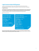
Logical servers and portability groups Logical servers and portability groups are key concepts in the Matrix OE and are heavily used for achieving HP-UX OE migrations. A brief review is necessary to understand their role and how they are used in such operations. Logical servers A logical server is a set of configuration information that you create, activate (instantiate), and move across physical and virtual machines.
Figure 2. Activated logical server Logical servers can be divided into two categories: • Physical logical servers: to be activated on blade servers in an infrastructure with Virtual Connect modules. • Virtual logical servers: to be activated in a virtual machine hosted by a blade server or rackmount or a HP Superdome 2 Server.
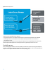
HP Matrix Operating Environment architecture Logical severs and portability groups are typical entities of the HP Matrix OE software stack. Figure 3 explains its global architecture, with the basement consisting of HP Systems Insight Manager (HP SIM) performing discovery, inventory, and monitoring of managed nodes. Figure 3.
Cross-technology moves: a complex problem Moving a complete OE (OS, applications, and data) to an unlike type of server may require the translation of meta-information not present in the logical server specification. This meta-information cannot be present in the logical server definitions since it is either specific to the underlying server where the OE is running or specific to the kernel of the activated OE. Either keep them “as-is” during the move or translate them to match the target.
Figure 4. Portable image execution during shutdown and boot phases Note: You can also use the HPPortableImage product to retain PPAs when performing a vPar/VM type transformation in an HP Integrity VM/vPar 6.x environment. Before changing the virtual server type (vm_type), issue kctune gio_portable_image=1 in the virtual server and shut it down gently. For more information on vPar/VM virtual server types, consult the HP-UX vPars and Integrity VM 6.1 administrator guide at hp.com/go/hpux-hpvm-docs.
The NPIV technology provides a unique and identical way for storage characterization in both physical and virtual infrastructures, by allowing virtual machines to use the Fiber Channel protocol for accessing the SAN. In a virtual context, WWNs are assigned to virtual Host Based Adaptors (vHBA) by the hypervisor. When activated on a physical HP blade server, the same WWNs can be associated to the physical HBAs by Virtual Connect modules.
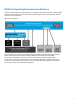
Figure 6, shows 2 SAN fabric connections: ATC_RACK and ATC_RACK0. The first one uses port 1 of the VC module in Bay6 and the second, port 1 of the VC located in Bay5. Figure 6. SAN fabric connections defined in VC modules To perform a P2V move of a physical logical server with ATC_RACK and ATC_RACK0 SAN fabrics connections, the LSM needs to find an NPIV capable device on the possible target hosts for both SAN fabrics.
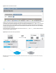
Figure 8. Virtual Connect Ethernet networks Networks connected to virtual machines can be defined and characterized by the virtual switches that they are connected to. Figure 9 shows virtual logical server LS1 connected to virtual switches Mgmt_1 and Prod_1. A move of this logical server toward a physical blade is possible only if LSM finds a target blade connected to the same physical networks.
Infrastructure requirements for cross-technology moves Fluid cross-technology offline moves, in a Matrix OE environment, are possible when the following requirements are met: • Potential HP Integrity VM hosts and physical Integrity blade targets are registered in the VMM. • NPIV technology is supported by HP Integrity VM hosts’ targets. • HP Integrity VM hosts’ hardware database is populated with SAN fabrics and registered in Matrix OE.
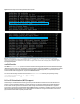
Figure 11.
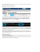
Number Active FlexFC VFC = 0 HPVM Virtual Fibre Channel (VFC) ---------------------------------Maximum Supported HPVM VFC = 16 Number Active HPVM VFC = 0 Populating an HP Integrity host database with SAN fabrics As explained earlier, the hardware database of potential HP Integrity VM host targets must be populated with the SAN fabrics defined in the Virtual Connect modules.
Figure 12.
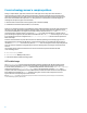
Creating a portability group with Virtual Connect Servers and HP Integrity VM hosts The potential physical servers and HP Integrity VM hosts’ targets for V2P and P2V migrations must be part of the same portability group. From the HP Matrix OE Visualization, select Modify Logical Server Portability Groups, and click on Create Group. Fill the Group Name and Group Description fields and then, in the Targets Table, tick the Server with Virtual Connect domain group as well as desired HP Integrity VM hosts.
Click on the Add Volume button; specify a Size (i.e., 31 GB) and the RAID level (i.e., RAID 5). Then, provide a Storage Port WWN identifying the SAN controller that will provide storage capacity for this SPE. To keep this example simple, we will supply only one SAN controller WWN. In the LUN field, provide the LUN identifier that will be used by the SAN controller during the logical server activation. Use the 16 hexadecimal digits Volume Set Addressing (VSA) format for this field.
Virtual to physical and physical to virtual offline moves In this paragraph, we will discuss the different steps needed to perform virtual to physical and then physical to virtual moves. The first operation consists of creating a logical server called v2p2v_ls in the unlike portability group created earlier. It will be activated first in a virtual machine. After the deployment of HP-UX in this virtual machine, we will perform a V2P offline move.
In the next step, click the Add Network button; select an Ignite-UX bootable network in port 1 from the Network Name pull down list. Add other networks at your convenience and click on Next. Note: The PXE Enable/Disabled switch has no action on HP-UX logical servers and can be left with the default (Disabled). In step 5, review the logical server summary carefully and click on Finish.
Figure 18. Virtual logical server activation Note: The different steps of logical server activation on a HP Integrity VM host can be viewed on the host with the command: tail -f /var/opt/hpvm/common/command.log The activated logical server appears in green from the Logical Server perspective of the HP Matrix OE visualization as shown in figure 19. The status is grayed and the utilization bars don’t mention any activity, since there is no operating system running yet in the virtual machine. Figure 19.
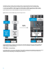
Figure 20. Configuring HP AVIO Stor EFI drive to enumerate all FC LUNs Verify that the HP-UX OE, which is going to be installed on this system, contains the HPPortableImage bundle, then proceed to the installation using your preferred method. Note: The HPPortableImage bundle is selected by default starting with HP-UX 11i v3, March 2012. For previous HP-UX versions, manually select it or download it from software.hp.com.
Figure 22. Steps achieved during a V2P offline move P2V offline move Performing a P2V offline move is very similar to a V2P migration since the same components are involved, but in a different order.
Figure 24 lists the different steps performed by the vmVirtProvider, LSM/VMM, and VCEM/VCM. The physical server is powered-off and its associated Virtual Connect profile is unassigned. Meta-information (i.e., EFI boot entries) and the logical server definition are sent to the vmVirtProvider of the target HP Integrity VM host. It adapts and translates this information to a virtual environment (i.e., boot hardware path) and creates a virtual machine (or register if already existing in NR mode).
Log into the source physical logical server, verify that the HPPortableImage depot is installed (install it if needed) and set the gio_portable_image kernel parameter to 1: kctune gio_portable_image=1 Perform a clean shutdown to save the network instances in the persistent KRS database. From the HP Matrix OE Visualization, select the physical logical server to move and click on the ToolsLogical Servers…Move… menu. The list of all potential targets appears with Profile Move as Operation type (Figure 25).
Summary HP Converged Infrastructure constantly improves and includes new features and capabilities helping IT departments to sustain customer demands. Leveraging HP Matrix Operating Environment and its ability to perform seamless migrations of HP-UX workloads in the data center dramatically increases the flexibility of the placement of those workloads, while preserving a constant level of service and simplifying development lifecycles.