
HP-UX vPars and Integrity VM V6.3 Administrator Guide
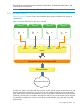
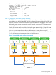

Ports on a vswitch that are configured for the same VLAN ID can communicate with each other.
Ports on a vswitch that are configured for different VLAN IDs are isolated from each other. Ports
on a vswitch that do not have any VLAN ID assigned cannot communicate with ports that have a
VLAN ID assigned, but can communicate with other ports that do not have VLAN ID assigned. The
port IDs for a vswitch can range 0 to 511.
The AVIO network vNIC is presented to guest operating system as PCI-X 1000Base-T with the
speed of physical network interface card backing the vswitch. The AVIO emulation can lead to an
incorrect calculation of vNIC performance by some network performance application on the guest.
To accurately calculate vNIC performance, consider the speed of the backing device on the Integrity
VSP.
If the guest must communicate with the VSP or outside the VSP over a VLAN, additional configuration
is necessary. For communication with the VSP, configure a VLAN interface on the VSP interface
for that vswitch. This VLAN interface must have the same VLAN ID as the guest port. For more
information about configuring VLANs on the VSP, see the Using HP-UX VLANs manual. You must
not use the hpvmnet command to create a virtual switch that is associated with a VLAN port on
the VSP (that is, a LAN created with nwmgr -a -S vlan or lanadmin -V). This “nested VLAN”
configuration is not supported.
Frames arriving at the vswitch from a guest can be “tagged” by the vswitch. Tagging consists of
inserting the VLAN ID information into the MAC header before forwarding the frame. Tagged
frames destined for a guest are always stripped of the tag information in the frame before being
forwarded. For Integrity VM, only tag-unaware guests are supported.
To configure a VLAN:
1. Create and start the vswitch. For example, to create and boot vswitch vmlan4 on lan1, enter
the following command:
# hpvmnet -c -S vmlan4 -n 1
# hpvmnet -b -S vmlan4
2. Use the hpvmnet command with the —u option to create the port, and assign it a VLAN ID.
For example, to create ports 1 and 2 for VLAN 100, enter the following command:
# hpvmnet -S vmlan4 -u portid:1:vlanid:100
# hpvmnet -S vmlan4 -u portid:2:vlanid:100
3. Add the vswitch ports to the guest configuration using the hpvmmodify command. For
example, to add the new VLAN ports to guests vm1 and vm2, enter the following command:
# hpvmmodify -P vm1 -a network:avio_lan::vswitch:vmlan4:portid:1
# hpvmmodify -P vm2 -a network:avio_lan::vswitch:vmlan4:portid:2
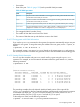
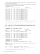
The output of the following command shows the resulting configuration:
# hpvmnet -S vmlan4
Name Number State Mode PPA MAC Address IP Address
======== ====== ======= ========= ====== ============== ===============
vmlan4 2 Up Shared lan4 0x00127942fce3 192.1.2.205
[Port Configuration Details]
Port Port Untagged Number of Active VM
Number state VLANID Reserved VMs
======= ============ ======== ============ ============
1 Active 100 2 vm1
2 Active 100 1 vm2
3 Active none 2 vm1
4 Active none 1 vm2
The two VMs, vm1 and vm2, have access to the virtual switch vmlan4 and are active on VLAN
100. Specifically, port 1 (guest vm1) and port 2 (guest vm2) can communicate with each other.
Port 1 (guest vm1) and port 4 (guest vm2) cannot communicate with each other.
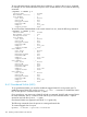
The hpvmnet command displays the following information about the VLAN ports:
122 Creating virtual and direct I/O networks