HP Value Thermal Printer User Guide
© 2014 Hewlett-Packard Development Company, L.P. Microsoft and Windows are U.S. registered trademarks of the Microsoft group of companies. The information contained herein is subject to change without notice. The only warranties for HP products and services are set forth in the express warranty statements accompanying such products and services. Nothing herein should be construed as constituting an additional warranty. HP shall not be liable for technical or editorial errors or omissions contained herein.
About This Guide This guide provides information on setting up and using the HP Thermal Receipt Printer. WARNING! Text set off in this manner indicates that failure to follow directions could result in bodily harm or loss of life. CAUTION: Text set off in this manner indicates that failure to follow directions could result in damage to equipment or loss of information. NOTE: Text set off in this manner provides important supplemental information.
iv About This Guide
Table of contents 1 Product Features ............................................................................................................................................ 1 HP Value Thermal Printer .................................................................................................................... 1 Identifying User Controls ...................................................................................................................... 2 Identifying Rear Connectors ............
Remote Diagnostics ........................................................................................................... 17 Solving Common Problems ................................................................................................................ 18 Online Technical Support ................................................................................................................... 21 Preparing to Call Technical Support ..............................................................
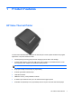
1 Product Features HP Value Thermal Printer The HP Value Thermal Printer is designed to work with point of sale system hardware and program applications.
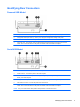
● Paper out sensor ● Software and product documentation provided on the HP Point of Sale System Software and Documentation disc Identifying User Controls 1 Receipt cover - Snap opens to easily drop the paper roll in place. 2 Status LED - the green LED indicates basic information about the printer status. A steady green light indicates the printer is on and operating normally. A flashing LED indicates the printer needs operator assistance.
Identifying Rear Connectors Powered USB Model 1 USB power connector - connects the printer to the POS computer and provides power to the printer. 2 Configuration switch (DIP switch 1) - allows you to change the configuration settings of the printer. 3 Cash drawer connector - connects the printer to the cash drawer. 4 Connector cover - the connector cover provides protection and strain relief for the printer connectors and cables.
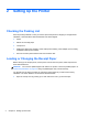
2 Setting Up the Printer Checking the Packing List Save the packing materials in case you need to repack the printer for shipping or storage. Before installation, check that all the items listed below have been shipped.
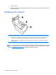
2. Loading: Remove the test printout (2) and starter roll thermal paper (3). Slide the supports off the roll (4). Changing: Remove the used paper roll. 3. Tear a clean edge on the new receipt paper roll, making sure the tape has been completely removed. 4. Place the receipt paper into the paper compartment so it unrolls from the bottom (5). Leave a few inches of paper sticking out of the printer. 5. While holding the paper in place, close the receipt cover (6).
Connecting the Cables NOTE: Place the printer on a level surface and position it in a location that allows access to cables, room to open the cover and away from traffic areas to limit the chance of being bumped or damaged. CAUTION: Connect cables to the printer before turning on power to the POS computer. The POS computer should always be turned off before connecting the communication cable. 1. Turn off the POS computer. 2. Open the connector cover on the rear of the printer to locate the connectors.
4. Plug the cash drawer cable into the cash drawer connector (RJ12) on the printer and the other end of the cable (RJ45) into the interface connector on the cash drawer. NOTE: The cash drawer cable is not included with the printer. 5. Close the connector cover on the rear of the printer, ensuring that all cables are aligned with the slots provided for each connector. Turning on the Printer After connecting the cables to the printer and POS computer, turn on the POS computer.
4. Close the receipt cover, continually holding the paper feed button until the configuration printout begins. For additional instructions on configuring the printer, refer to Operating the Printer on page 10. Extending Your Character Sets and Fonts The following character sets and code pages are available for this printer. Most models come with the code preinstalled. To confirm which code pages are resident, print out the Diagnostic form (refer to Chapter 3 for instructions).
● Code Page 1252 Windows Latin 1 ● Code Page 1255 Hebrew Extending Your Character Sets and Fonts 9
3 Operating the Printer Configuring the Printer The configuration menu allows you to set general printer parameters. The test prints the diagnostics form, which details settings for all functions. The printer will partially cut the paper between each variation. The test ends with a partial cut of the paper. A complete test printout may require the use of several feet of paper. Since the printer is usually shipped pre-configured, most users do not need to change the configuration of the printer.
6. Turn on power to the printer and immediately press and hold the paper feed button (3) until the configuration printout begins. ● The printer beeps, then prints the diagnostics form and prints instructions for entering the configuration menu. Follow the instructions. ● The printer pauses and waits for a main menu selection to be made (see sample printout on the following page in this chapter; short clicks are used, except when answering Yes or validating selection). 7.
Print test and Configuration menu samples. (Shown approximately 60% of size.) Short clicks are used in the main menu selections.
Monochrome Paper Print Density (Default) This function makes it possible to adjust the energy level of the printhead to darken the printout or adjust for paper variations. An adjustment should only be made when necessary. The factory setting is 80%. CAUTION: Choose an energy level no higher than necessary to achieve a dark printout. Failure to observe this rule may result in a printer service call or voiding of the printer warranty. Running at a higher energy level will reduce the printhead life.
Keep in mind that the ambient temperature may be affected by factors such as direct exposure to sun or close proximity to heating elements. CAUTION: When the duty cycle exceeds the limits shown in the following table, the receipt printhead will heat up and shut down. This may damage the printhead. To avoid this problem, do one or a combination of the following: 1. Reduce the amount of coverage. 2. Reduce the time of continuous solid printing. 3. Reduce the ambient temperature.
4 Maintenance Guidelines Cleaning the Printer Clean the outside of the cabinet as needed to remove dust and finger marks. Use any household cleaner made for plastics. Test it first on a small unseen area. Clean the printer paper bucket with a clean, damp cloth.
A Troubleshooting Diagnostics The printer performs three primary diagnostic tests that provide useful information about the printer’s operating status: ● Startup diagnostics, performed during the printer’s startup cycle ● Runtime diagnostics ● Remote diagnostics, maintained during normal operation and reported in the print test Startup Diagnostics When the printer receives power or performs a hardware reset, it automatically performs the startup diagnostics (also known as level 0 diagnostics) during
If the printer has not been turned on before, or a new EEPROM has been installed, the default values for the printer functions will be loaded into the EEPROM during startup. Runtime Diagnostics Runtime diagnostics (sometimes called level 2 diagnostics) run during normal printer operation. When the following conditions occur, the printer automatically turns off the appropriate motors and disables printing to prevent damage to the printer.
● Number of times the cover is opened ● Maximum temperature reached Solving Common Problems The following table lists possible problems, the possible cause of each problem, and the recommended solutions. Problem Possible Cause Solution Green LED, quick continuous flashing. Paper is out. Load a new paper roll. Refer to Setting Up the Printer on page 4. Receipt cover open. Close the cover. Knife unable to home. Stop using the printer. Check the knife to see if it needs to be replaced.
Problem Possible Cause Solution Receipt is not cut. Paper is jammed. Open the receipt cover, inspect the knife, and clear the jammed paper. The knife is not enabled. Enable the knife in the configuration menu. Refer to Operating the Printer on page 10. Paper roll is loaded incorrectly. Check that the paper is loaded properly. Thermal printhead is dirty. Clean thermal printhead with rubbing alcohol. Use the recommended thermal receipt paper.
Problem Possible Cause Solution Printer does not function when turned on. The printer is not plugged in. Check that printer cables are properly connected at both ends. Check that the POS computer is turned on. Receipt cover is not fully closed. Close and latch the receipt cover. DIP switch 2 has been left in the ON position. Return DIP switch 2 to the OFF (up) position. Printer is not correctly configured. Check the printer’s configuration and reconfigure if necessary.
Online Technical Support For the online access to technical support information, self-solve tools, online assistance, community forums or IT experts, broad multivendor knowledge base, monitoring and diagnostic tools, go to http://www.hp.com/support. Preparing to Call Technical Support HP provides hardware break/fix support for this product. If you can not solve a problem using the troubleshooting tips in this section, you may need to call technical support.
B Technical Specifications HP Value Thermal Printer Printer Specifications Reliability MCBF Printlines 72 million MCBF Knife Cuts 3 million Interface Powered USB (some models) USB or Serial (some models) Memory 2 MB flash memory, 512K RAM Dimensions and Weight Height 134 mm (5.34”) Width 144 mm (5.66”) Depth 184 mm (7.24”) Weight 1.3 kg (2.9 lbs) Power Requirements Operating Voltage 24Vdc +/- 10% +5 volts for logic circuit Power Consumption 2.
Transit: Temperature 40°C to 60°C (-40°F to 140°F) Humidity 5% to 95% Condensation Condensation may occur when the printer is moved from cold to warm areas after shipment. The printer’s design permits operation after drying out and stabilizing at room temperature.
Print Size Character sizes for the standard and compressed mode: ● Standard 15.6 characters per inch 44 characters per line 13 x 24 dots cell size ● Compressed 20.3 characters per inch 56 characters per line 10 x 24 dots cell size Ordering Thermal Paper The printer requires qualified thermal paper with the following dimensions: Width Diameter Length 80 ± 0 .2 mm (3.15 ± 0.01 in.) 90 mm max. (3.54 in.) 98 meters (322 ft.) nominal The above figures are based on a core diameter of 22 ± 0 .5 mm (0.
Monochrome (Black Ink) Paper Qualified Manufacturer Paper Grade (Density) Appleton Papers, Inc. (USA) Optima T1030 (Light) 825 E. Wisconsin Avenue Optima T1012A (Standard) Appleton, WI Optima POS-Plus (Light) Voice: (800)922–1729 Optima T2162(Light) Fax: (800)922–1712 Optima Superior (Standard) Optima Hi-Yield Kanzaki Specialty Papers (USA) P–300 (Light) 20 Cummings St.
26 ● Top margin to manual tear-off: 17.8 mm (0.70 inches) ● Top margin to knife cut: 19.0 mm (0.
C Agency Regulatory Notices Federal Communications Commission Notice This equipment has been tested and found to comply with the limits for a Class B digital device, pursuant to Part 15 of the FCC Rules. These limits are designed to provide reasonable protection against harmful interference in a residential installation.
Hewlett Packard Company P. O. Box 692000, Mail Stop 530113 Houston, Texas 77269-2000 Or, call 1-800-HP-INVENT (1-800 474-6836) For questions regarding this FCC declaration, contact: Hewlett Packard Company P. O. Box 692000, Mail Stop 510101 Houston, Texas 77269-2000 Or, call (281) 514-3333 To identify this product, refer to the Part, Series, or Model number found on the product.
Japanese Notice Korean Notice Product Environmental Notices Disposal of Waste Equipment by Users in Private Household in the European Union This symbol on the product or on its packaging indicates that this product must not be disposed of with your household waste. Instead, it is your responsibility to dispose of your waste equipment by handing it over to a designated collection point for the recycling or waste electrical and electronic equipment.
Restriction of Hazardous Substances (RoHS) A Japanese regulatory requirement, defined by specification JIS C 0950, 2005, mandates that manufacturers provide Material Content Declarations for certain categories of electronic products offered for sale after July 1, 2006. To view the JIS C 0950 material declaration for this product, visit http://www.hp.com/go/jisc0950.
Product Environmental Notices 31
Turkey EEE Regulation In Conformity with the EEE Regulation EEE Yönetmeliğine Uygundur Ukraine Restriction of Hazardous Substances The equipment complies with requirements of the Technical Regulation, approved by the Resolution of Cabinet of Ministry of Ukraine as of December 3, 2008 No. 1057, in terms of restrictions for the use of certain dangerous substances in electrical and electronic equipment.