
User Guide


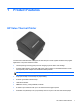
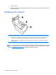

Identifying Rear Connectors
Powered USB Model
1 USB power connector - connects the printer to the POS computer and provides power to the printer.
2 Configuration switch (DIP switch 1) - allows you to change the configuration settings of the printer.
3 Cash drawer connector - connects the printer to the cash drawer.
4 Connector cover - the connector cover provides protection and strain relief for the printer connectors and
cables. This cover should remain on the printer and cables routed as described in Chapter 2.
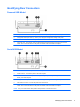
Serial/USB Model
1 USB connector - connects the printer to the POS computer.
2 Serial connector - connects the printer to the POS computer.
3 Power connector - connects the printer to the power adapter for power. If provided, a power cable can connect
directly to the POS computer.
4 Configuration switch (DIP switch 1) - allows you to change the configuration settings of the printer.
5 Cash drawer connector - connects the printer to the cash drawer.
6 Connector cover - the connector cover provides protection and strain relief for the printer connectors and
cables. This cover should remain on the printer and cables routed as described in Chapter 2.
NOTE: Only one communication cable (USB or Serial) should be connected at one time.
Identifying Rear Connectors 3