
HP Virtual Connect 1Gb Ethernet Cookbook

Single Domain/Enclosure Scenarios
Overview
This chapter will provide several simple configuration scenarios of Virtual Connect, using a Single HP
BladeSystem c7000 enclosure with two Virtual Connect Ethernet modules installed in Bays 1 and 2. Each scenario
will provide an overview of the configuration, show how to complete that configuration and include both GUI and
CLI (scripted) methods. Where possible, examples for Windows and/or VMware will also be provided.
Requirements
This chapter will utilize a single HP BladeSystem c7000 enclosure with TWO Virtual Connect Ethernet modules
and a half height BladeSystem Server. The server will connect to the Virtual Connect models with two 1Gb NICs.
NIC 1 will connect to the VC module in Bay 1 and NIC 2 will connect to the VC module in Bay 2.
A pair of managed network switches should also be provided, the switches should also be trunked together.
It is assumed that a Virtual Connect Domain has been created either through the GUI or a CLI script and no VC
Networks, uplink sets or Server Profiles have been created.
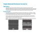
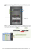
Figure 5 - c7000 Enclosure with Sixteen (16) Half Height Gen 8 BladeSystem servers, two Virtual Connect 1/01-F
Ethernet modules in rear bays 1 & 2, and two Virtual Connect 4Gb FC modules in rear Bays 3 & 4.