
HP Virtual Connect 1Gb Ethernet Cookbook

Scenario 3 – Multiple Simple Networks Providing Redundancy and Link Aggregation 802.3ad (LACP) with VLAN Tunneling
– VMware ESX 43
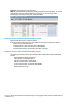
Summary
We created two VC networks, both with TWO active uplinks. Both VC Networks will pass several
VLANs as configured/defined by the connected switch, without modification or interpreting the
VLAN tags.
When VC profile ESX-1 is applied to the server in bay1 and is powered up, it has two NICs, these
NICs are connected to “vNet-PROD-1” and “vNet-PROD-2” respectively, which connects to the
network infrastructure through uplinks. These NICs could be configured within the OS as
individual NICs with their own IP address or as a pair of TEAMED NICs or connected to the same
vSwitch. Either NIC could be active. As a result, this server could access the network through
either NIC or either set of uplink cables, depending on which NIC is active at the time.
When additional bandwidth is required, additional uplinks could be added to each vNet.
If additional VLANs need to be supported by these vNets, simply configure the upstream switch
ports for the new VLANs, then configure the ESX vSwitch with additional port groups to support
these VLANs, no additional Virtual Connect configuration is required.
As additional servers are added to the enclosure, simply create additional profiles, configure the
NICs for vNet-PROD-1 and vNet-PROD-2 and apply them to the appropriate server bays.
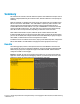
Results
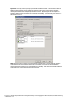
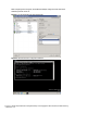
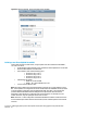
The following graphic provides an example of an ESX server with TWO NICs connected to the
same vSwitch, the console is configured for VLAN 101, which was the Default (untagged) VLAN.
Additional port groups were configured to support each additional VLAN. VMotion has been
configured on VLAN 110 and is tagged.
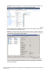
Figure 37 - As VLAN-101 was set as Untagged at the switch port, you need to ensure that the
Hypervisor in NOT configured for VLAN tagging. However, if you want to put this server onto a
VLAN that is tagged, this setting will need to be configured for that VLAN.