HP Virtual Connect for c-Class BladeSystem Version 2.
© Copyright 2009 Hewlett-Packard Development Company, L.P. The information contained herein is subject to change without notice. The only warranties for HP products and services are set forth in the express warranty statements accompanying such products and services. Nothing herein should be construed as constituting an additional warranty. HP shall not be liable for technical or editorial errors or omissions contained herein. Microsoft is a U.S. registered trademark of Microsoft Corporation.
Contents Introduction .................................................................................................................................. 6 Virtual Connect documentation.................................................................................................................... 6 Overview..................................................................................................................................... 7 Virtual Connect overview.......................................
SNMP Settings (SNMP FC Settings).................................................................................................. 45 System Log screen ................................................................................................................................... 46 System Log Configuration ......................................................................................................................... 47 Network management .......................................................
Server Profiles screen ............................................................................................................................. 110 Edit a Server Profile (single profile) screen ................................................................................................ 111 Edit a Server Profile (Inline)..................................................................................................................... 114 View printable report ......................................
Introduction Virtual Connect documentation The following Virtual Connect documentation is available on the HP website (http://www.hp.com/go/bladesystem/documentation): • HP Virtual Connect for c-Class BladeSystem User Guide This guide provides details for the Virtual Connect GUI, including descriptions of screen contents and steps to set up domains, profiles, networks, and storage.
Overview Virtual Connect overview Virtual Connect is a set of interconnect modules and embedded software for HP BladeSystem c-Class enclosures that simplifies the setup and administration of server connections.
connection. With this configuration, the administrator can use Virtual Connect Manager to deploy and migrate a server blade profile to any server in the Virtual Connect domain without changing external LAN or SAN configurations. Using multiple enclosures Multiple enclosure support enables up to four c7000 enclosures to be managed within a single Virtual Connect domain for a total of 128 servers, if double-dense support is enabled. Multiple enclosure domains are not supported on c3000 enclosures.
HP Virtual Connect Manager Configuring browser support Access to the application must be through HTTPS (HTTP exchanged over an SSL-encrypted session). For optimal viewing, HP recommends setting the screen resolution to 1280 x 1024. Requirements The HP Virtual Connect Manager Web interface requires an XSLT enabled browser with support for JavaScript 1.3 or equivalent. The following browsers are supported: • Microsoft® Internet Explorer 6.x or 7.x • Mozilla Firefox 2.x or 3.
Always apply relevant licenses that are dependent on MAC addresses after the server profiles are assigned so that the licenses are not lost due to a change in MAC address. IMPORTANT: If you plan to use RDP for RedHat Linux installation and also plan to use User- or HP-defined MAC addresses, you must import the enclosure before running RDP.
Command line overview The HP Virtual Connect Manager Command Line Interface can be used as an alternative method for managing the Virtual Connect Manager. Using the CLI can be useful in the following scenarios: • HP Management Applications (for example, Systems Insight Manager or Insight Control tools) can query the Virtual Connect Manager for information these tools need to present a complete management view of HP BladeSystem enclosures and devices.
Possible causes for logon problems: • The information is not being entered correctly. User names and passwords are case-sensitive. • The account being entered is not an account for HP Virtual Connect Manager. • The account being entered has been deleted, disabled, or locked out. • The password for the account needs to be changed. • There is no connection to the Virtual Connect Ethernet module running the active Virtual Connect Manager.
About HP Virtual Connect Manager To view detailed product information, select About HP Virtual Connect Manager from the Help pull-down menu. Navigating the HP Virtual Connect Manager GUI Navigation overview The HP Virtual Connect Manager navigation system consists of a tree view on the left side of the page that lists all of the system devices and available actions. The tree view remains visible at all times.
Menu item Links to Network Setup Wizard Welcome screen for the Network Setup Wizard Fibre Channel Setup Wizard Welcome screen for the Fibre Channel Setup Wizard Server Profile Wizard Welcome screen for the Server Profile Wizard Backup/Restore Domain Configuration Domain Settings (Backup/Restore) screen (on page 29) System Log System Log screen (on page 46) Export Support Information Support log ("Export support information" on page 21) Reset Virtual Connect Manager Reset Virtual Connect Manag
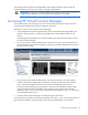
To select the device and open the device detail page, click the link for an individual device. Individual device pages contain detailed information about the selected device and any other functions related to that device. Domain Status summary The Domain Status summary provides a count of Virtual Connect elements that are in an alert status other than OK. Virtual Connect elements summarized here include networks, shared uplink sets, server profiles, interconnect modules, and server blades.
To view a summary of systems that have an alert icon displayed, click the Domain Status link. See "Domain Status screen (on page 17).
Domain Status screen This screen provides an overall domain status and a detailed summary of systems that currently have an alert status other than OK. To view detailed information about a device, click that device name in the list. Additional information on the issue might be available as a tooltip for the severity icon. To see this information, mouse over the severity icon. For information on specific status error messages, see "Status error messages (on page 17).
Possible cause: The management application running on the active VC-Enet module is an earlier version than the backup VC-Enet module. If there is a failover to the backup module, the domain will lose its redundancy because the later firmware on the current backup will upgrade the configuration database and cause it to be unreadable by the earlier version. Action: Upgrade the backup module to the same firmware version as is running on the active module.
To display the Enclosures View screen, click Hardware Overview in the left window.
Enclosures view (multiple enclosures) When more than one enclosure has been imported, each enclosure is displayed on the Enclosures View screen. Status icon definitions Icon Status Description Critical A device or system is indicating a potential outage. Incompatible A profile is incompatible with assigned hardware. / Mismatch Missing A device or item is missing. Major A device or system is degraded. Minor A device or system is degraded. Disabled A device or item is disabled.
Icon Status Description Informational — Other icon definitions Icon Description Click to edit the properties of this line item. Click to delete this line item. Mouse over to view specific help for the associated field. The UID/PID of this line item is unlit. The UID/PID for this line item is lit. Click to copy the properties of this line item, to define a new profile. The server blade is powered on. (green) The server blade is powered off. (amber) Click to save the edit changes for this line item.
• Operating system status information • Directory listings • Boot Loader environment variables Reset Virtual Connect Manager Users must have Administrative privileges to reset the Virtual Connect Manager. In a multi-enclosure environment, the Ethernet modules in bays 1 and 2 of the primary enclosure host the Virtual Connect Manager.
Domain management Domain overview A basic Virtual Connect domain includes a single HP c-Class BladeSystem c7000 Enclosure for a total of 16 servers (or up to 32 servers if the double-dense option is enabled), or a single HP c-Class BladeSystem c3000 Enclosure for a total of 8 servers (or up to 16 servers if the double-dense option is enabled).
and/or Shared Uplink Set, the module can be removed from the Virtual Connect domain. A FC module can be administratively removed when none of its fabrics are in use by a profile. For additional information, see "Interconnect Bay summary screen (Ethernet module) (on page 129)" and "Administrative module removal (on page 141)." The following table describes the available actions in the Domain Settings (Domain Configuration) screen.
1. Power off all servers that are associated with profiles. See "Server Bay Status screen (on page 149)." 2. Navigate to the Domain Settings (Domain Configuration) screen (on page 23). 3. Click Delete Domain. A domain name verification window is displayed. 4. Enter the name of the domain to be deleted. This should be the name of the domain you are currently logged into, displayed in the Virtual Connect Domain Name box on the Domain Settings (Domain Configuration) screen (on page 23). 5. Click OK.
The following table describes the available actions in the Domain Settings (Domain IP Address) screen. Clicking another link in the pull-down menu or left navigation window causes current edits that have not been applied to be lost. Task Action Use a domain IP address Select the box next to Use Domain IP address, and then enter the IP Address, Subnet Mask, and Gateway. Clear unsaved changes on the screen Click Clear. Save changes and remain on this screen Click Apply.
Adding and importing a remote enclosure Adding and importing a remote enclosure requires full domain and server privileges. Virtual Connect Manager supports up to four c7000 enclosures in a single domain. To add a remote enclosure: 1. Click Find on the Domain Settings (Domain enclosures) screen ("Domain Settings (Domain Enclosures)" on page 26). 2. Type in the following information: o OA IP Address o OA User Name o OA Password 3. Click OK. 4. Select the box next to the discovered enclosure.
5. Click Import.
Virtual Connect Manager imports the enclosure and provides status information. Domain Settings (Backup/Restore) screen Use this screen to create a backup file of the Virtual Connect domain configuration or to restore a configuration that has been lost. The domain configuration includes network definitions, MAC address settings, WWN settings, Fibre Channel fabric settings, local user accounts, and server profile definitions.
To back up a domain configuration: 1. Click Backup Configuration. 2. Navigate to the hard drive location for the backup file. 3. Name the file (usually the domain name), and then click Save. To restore a domain configuration: 1. Enter or browse to the backup file. 2. Select the file. 3. Select the Ignore enclosure serial number in restored configuration file checkbox to restore a configuration that was generated on another enclosure.
Domain Settings (Firmware Management) screen To update the Virtual Connect Ethernet module firmware, select Firmware Update from the Tools pull-down menu, or click Firmware Management in the left window. The automated firmware update process simplifies administration and minimizes network downtime and outage by upgrading and activating all non-Active Virtual Connect Ethernet modules in an optimized manner.
2. o Enter a local file name in the File field, or click Browse to find a local file, and then click Upload. o Enter the URL location of the firmware update, and then click Upload. The Firmware Management screen appears. TIP: Click on the firmware description link to view release notes for this version. 3. Update the firmware using one of the following methods: o Click Automated Update. o Click Update in the row of each module to be updated.
However, the Administrator password can be changed. The default Administrator password is identified on the Default Network Settings label on the VC-Enet module in bay 1 of the enclosure. To reset the Administrator password to the factory default, see the information on resetting the administrator password and DNS settings in the HP Virtual Connect for c-Class BladeSystem Setup and Installation Guide.
Column Description User Name The user name must begin with a letter and is case sensitive. Privileges Shows what privileges the user has (Domain, Network, Storage, and/or Server) Full Name The user's full name. All users can modify their own full name. Contact Contact information for the user account. The contact information can be the name of an individual, a telephone number, or other useful information. All users can modify their own contact information.
Add new user Observe the following user settings guidelines: • Username is a required field. • Username must contain an alpha-numeric value with 1 to 13 characters. • Password must contain an alpha-numeric value with 3 to 40 characters.
• • • o Update firmware o Administer SSL certificates o Delete the VC domain o Save configuration to disk o Restore the configuration from a backup Networking o Configure network default settings o Select the MAC address range to be used by the VC domain o Create, delete, and edit networks o Create, delete, and edit shared uplink sets Server o Create, delete, and edit server Virtual Connect profiles o Assign and unassign profiles to device bays o Select and use available networks
Directory Settings (Directory Server) screen This screen enables Administrators to set up an LDAP server to authenticate users accessing the CLI or GUI based on user name, password, and role. Beginning with version 1.31 of Virtual Connect Manager, users can test an LDAP configuration before applying it. For more information, see "Test LDAP authentication (on page 40)." The following table describes the fields within the Directory Settings (Directory Server) screen.
Directory Settings (Directory Groups) screen Use this screen to manage the Directory Group settings for Virtual Connect Manager. The following table describes the fields within the Directory Settings (Directory Groups) screen. Field Description Checkbox Used to select Directory Group for editing or deleting Group Name This is the Directory Server group name. Microsoft Active Directory servers have a reverse mapping from the user to the groups the user is a member of.
Add LDAP Group Use this screen to add a Directory Group. The following table describes the fields within the Add LDAP Group screen. Field Description Group Name This is the Directory Server group name. Microsoft Active Directory servers have a reverse mapping from the user to the groups the user is a member of. Other servers might need to combine the Group Name with a Search Context to look up the group, to determine if the user is a member of the group. Starting with Virtual Connect v1.
• Install a certificate that exactly matches the certificate provided by the Directory Server. To upload a certificate, select the certificate from the list, and then click Certificate Upload. If no certificates are installed, no authentication of the Directory Server is performed (although the connection to the Directory Server must be established using SSL). The following table describes the columns within the Directory Settings (Directory Certificate) screen.
The status window displays any problems encountered during the test. When testing is complete, click Close. SNMP and SMI-S overview SNMP is used by network management systems to monitor network-attached devices for conditions that warrant administrative attention. SNMP consists of a set of standards for network management, including an Application Layer protocol, a database schema, and a set of data objects.
• Compaq System Info MIB • RFC 3418 SNMPv2-MIB • RFC 2863 IF-MIB • RFC 4188 BRIDGE-MIB The VC-Enet module supports the following SNMP traps: • cpqHoSWRunningStatusChangeTrap from CPQ-HOST MIB The VC domain status has changed as described in the next section. • coldStart trap from SNMPv2-MIB CRITICAL—A coldStart trap signifies that the SNMP agent is reinitializing itself and that its configuration might have been altered.
• connUnitPortStatusChange (1.3.6.1.3.94.0.6) INFO—The overall status of the connectivity unit has changed. Sent whenever any of the following notifications occur: • o UserPort.StateChange o UserPort.OperChange coldStart CRITICAL—A coldStart trap signifies that the SNMP agent is reinitializing itself and that its configuration might have been altered.
The VC-Enet SNMP settings apply to all VC-Enet modules in the Virtual Connect domain. The following table describes the fields within the SNMP Settings (SNMP Enet Settings) screen. Field name Description Enable SNMP Select to enable SNMP System Contact Specify contact name for this system when SNMP is enabled Read Community Controls SNMP read access when SNMP is enabled. The default value for read community string is "public". The read community string must always be set when SNMP is enabled.
SNMP Settings (SNMP FC Settings) By enabling SNMP for VC-FC modules, network management systems can monitor the VC-FC modules in the domain for events such as warnings and errors that might require corrective actions. The user must have storage administrator privileges to administer SNMP FC settings. The VC-FC SNMP settings apply to all VC-FC modules in the VC domain. The following table describes the fields within the SNMP Settings (SNMP FC Settings) screen.
Field name Description Community String The Community String acts like a password for a given trap destination. The trap receiving application can use the community string to filter the incoming traps. Default: public To apply changes made on this screen, click Apply. System Log screen The System Log screen displays logged information of events within Virtual Connect Manager.
System Log Configuration Use this screen to view or set remote log destination settings. Column Description Log host The IP address or the DNS of the configured remote log destination Log severity Severity of the log messages that should be sent to the specified destination. Valid values include "Critical", "Error", "Warning", and "Informational". Transport The transport protocol to be used for sending the log messages to the destination. Valid values include "TCP" and "UDP".
To delete a remote log destination, select the checkbox next the preferred destination, and then click Delete.
Network management Networks overview The Virtual Connect Ethernet module uses standard Ethernet bridge circuitry with special firmware so that it functions as a configurable Ethernet port aggregator. For a specific external data center connection, only the selected server Ethernet NIC ports are visible on what appears to be an isolated, private, loopfree network.
Define Ethernet Network screen The Define Ethernet Network screen is accessible to all users with network privileges from the Define a Network link on the Virtual Connect Manager homepage or the Define pull-down menu. The following table describes the fields within the Define Ethernet Network screen.
Field name Description Connected to If the port is connected to a switch that supports LLDP, the switch MAC address and switch port are displayed. A link is provided to obtain more information about the far-end switch port. PID When selected, sets/clears the port identifier color as blue on the HP 1/10Gb VC-Enet module to aid in the location of the specific uplink. The PID status for the overall network is also displayed.
2. Select whether to enable (checked) or disable (unchecked) Smart Link (on page 49). 3. Select whether to designate (checked) or not designate (unchecked) this network as a private network ("Private Networks" on page 49). 4. Select whether to enable (checked) or disable (unchecked) VLAN tunneling ("Server VLAN Tagging Support" on page 65). This option is only available if the 'Tunnel VLAN Tags' radio button is selected on the Advanced Settings tab of the Ethernet Settings screen. 5.
This summary screen displays the external connections for each network and is available to all authorized users. The following table describes the columns within the summary table on the Ethernet Networks (External Connections) screen.
Task Action Define a new network Click Define Network. Illuminate the PID for all uplink ports Click on the circle next to the network in the list. associated with a network View a printable report Click View Printable Report. Edit Ethernet Network screen To access this screen, click the network name under the Ethernet Networks link in the left VC Manager navigation window. Use this screen to edit the properties of an existing network or to delete a network.
Field name Description Enable VLAN Tunneling Shows whether VLAN tunneling is enabled (checked) or disabled (unchecked) Status Displays the current status of the network PID PID status for the overall network State Displays the current state of the network (enabled or disabled) External Uplink Ports Use Shared Uplink Set Enables selection or creation of a shared uplink set Port Network port locations (enclosure, bay, and port numbers) Port Role Applicable when Failover Connection Mode is selec
Task Action Change the connection mode Click the down arrow in the box next to Connection Mode, and then select Auto or Failover. For a description of these modes, see "Defining a network (on page 51)." Delete an added port Click X in the Delete column for that port. View updated information on the network Click Refresh. Delete the network Click Delete. Clear unsaved changes on the screen Click Clear. Save changes and remain on this screen Click Apply.
Column name Description Port Shows the overall status of the individual server port as well as the port number within the server MAC Lists the MAC address for the server port Location Lists the enclosure and device bay for the server blade (when the profile is assigned to a device bay) Profile Shows the overall status of the associated server profile and the server profile name. Click the profile name to display the edit screen for the profile.
For additional information, see "MAC address settings (on page 58)." MAC Address Settings IMPORTANT: Configuring Virtual Connect to assign server blade MAC addresses requires careful planning to ensure that the configured range of MAC addresses is used once within the environment. Duplicate MAC addresses on an Ethernet network can result in a server network outage. Each server blade Ethernet NIC ships with a factory default MAC address.
• Virtual Connect automatically reserves both a primary address and an iSCSI MAC address for use by multifunction gigabit server adapters, such as the HP NC373m PCI Express Dual Port Multifunction Gigabit server adapter. Only the primary MAC address is used by standard (not multifunction) Ethernet devices.
Whenever port monitoring is enabled, a warning icon appears in the banner at the top of the page. If port monitoring is configured and enabled within the Virtual Connect domain, Ethernet data from the monitored ports is replicated on the network analyzer port, which poses a security risk and could result in network loops if not connected properly. The following table describes the fields within the Ethernet Settings (Port Monitoring) screen.
Field name Description Direction Direction of traffic on the port being monitored. Valid choices are From Server, To Server, or Both. The default is Both. Server Profile Identifies the server profile associated with the monitored port if one exists.
Select Monitored Ports screen The Select Monitored Ports screen is displayed when the Select Ports button is clicked on the Ethernet Settings (Port Monitoring) screen. You can select up to 16 server ports to monitor. The list of ports can be filtered by selecting one or more of the drop-down boxes at the top of the screen. The following table describes the available actions in the Select Monitored Ports screen. Task Action Select a port to be monitored Select the checkbox corresponding to the port.
Ethernet Settings (Advanced Settings) screen Use this screen to perform the following tasks: • Set Server VLAN Tagging Support (on page 65) • Use the Multiple Networks Link Speed Settings (on page 67) to set a custom value for preferred link connection speed or maximum link connection speed • Enable or disable MAC Cache Failover • Modify the refresh interval for MAC Cache Failover (on page 67) • Enable or disable IGMP Snooping (on page 68) • Modify the idle timeout interval for IGMP Snooping Ne
This screen can be changed only by users with server and network administrator privileges.
Server VLAN Tagging Support This option provides explicit VLAN tagging support for server links, enabling each server link to be shared among multiple networks. Users can map server VLAN-tagged Ethernet packets to specific networks, which is essential in deploying server virtualization applications such as a virtual operating system solution. The following figure shows tunneled VLAN tags. On the dedicated, green network, both uplink and server VLAN tags are tunneled through Virtual Connect unchanged.
The following figure shows mapped VLAN tags, a feature that enables users to define how each server VLAN tag is mapped to a specific network. Each server port can connect to multiple networks. Server NIC1 is connected to both the Green and Red networks. Server NIC2 is connected to the Red network, and Server NIC3 is connected to the Red, Blue, and Orange networks. All server NICs can send and received tagged or untagged traffic.
dedicated networks before the 'Map VLAN Tags' option can be selected. Before Virtual Connect v1.31, all networks had tunneling enabled. If you upgrade from a previous version, you cannot enable mapping of VLANs unless you disable tunneling on each network from the Edit Ethernet Network screen (on page 54). TIP: Use CLI scripting to automate the disabling of VLAN tunneling on multiple dedicated vNets. For information on CLI scripting, see the HP BladeSystem Virtual Connect Command Line Interface User Guide.
IMPORTANT: Be sure to set switches to allow MAC addresses to move from one port to another without waiting for an expiration period or causing a lock out. IGMP Snooping The IGMP Snooping feature allows VC-Enet modules to monitor (snoop) the IGMP IP multicast membership activities and configure hardware Layer 2 switching behavior of multicast traffic to optimize network resource usage. Currently only IGMP v1 and v2 (RFC2236) are supported.
Shared uplink sets and VLAN tagging A shared uplink set is a way of identifying Virtual Connect Ethernet module uplinks that will carry multiple networks over the same cable. In this case, each Ethernet packet carries a VLAN tag (IEEE 802.1Q) to identify the specific network to which it belongs. On shared uplinks, the VLAN tags are added when packets leave the VC-enabled enclosure and are removed when packets enter the enclosure.
For Virtual Connect v1.34 and Virtual Connect v2.10, a maximum of 64 associated networks is supported in each shared uplink set. All other versions support a maximum of 32 networks per shared uplink set. The following table describes the fields within the Define New Shared Uplink Set screen. Field name Description Ethernet Shared External Uplink Set Uplink Set Name Descriptive name for the shared uplink set. Do not use spaces.
Field name Description Associated Networks (VLANtagged) Network Name Displays the name of the associated networks VLAN ID Displays the VLAN ID number Native Select whether native VLAN is enabled (checked) or disabled (unchecked) Smart Link Select whether Smart Link is enabled (checked) or disabled (unchecked) Private Network Select to designate (checked) or not to designate (unchecked) this network as a private network Advanced Displays icon that accesses advanced network settings The followin
1. Enter the shared uplink set name. The uplink set name can be up to 64 characters in length (no spaces). 2. Add one or more external ports using the Add Port pull-down menu. Only available ports are listed, and they display the current port link status. Select two or more ports to ensure a high availability connection. 3. Select the speed and duplex (where applicable) of the uplink ports. Click the drop-down box under Speed, and then select a setting.
Use this screen to edit the properties of an existing shared uplink set, add/delete an associated network, or delete a shared uplink set. This screen has the same fields as the Define Shared Uplink screen. The screen can be edited only by users with network privileges, but it is viewable by all authorized users. The following table describes the fields within the Edit Shared Uplink Set screen.
Field name Description Speed/Duplex Pull-down menu to specify the speed and duplex (where applicable) of the uplink port. Half-duplex operations are not supported by the VC-Enet module. Delete Displays Delete icon. Click to delete that line item. Associated Networks (VLANtagged) Network Name Displays the name of the associated networks VLAN ID Displays the VLAN ID number Native Select whether native VLAN is enabled (checked) or disabled (unchecked).
Shared Uplink Sets (External Connections) screen To access this screen, click the Shared Uplink Sets link in the left VC Manager navigation window. This summary screen provides an overview of external shared uplink connections and access to the Associated Networks tab to view the mapping of networks to those uplinks. This screen is only applicable if multiple networks are being connected over a single external uplink set by the use of VLAN tagging.
This summary screen displays the mapping of networks to external shared uplink connections. This screen is only applicable if multiple networks are being connected over a single external uplink set by the use of VLAN tagging.
Storage management Storage overview The Virtual Connect Fibre Channel modules enable the c-Class administrator to reduce FC cabling by making use of N_Port_ID virtualization (NPIV). The HP VC-FC acts as an HBA aggregator where each NPIV-enabled N-port uplink can carry the FC traffic for multiple HBAs. Because it uses an N-port uplink, it can be connected to data center Brocade, McData, Cisco, and Qlogic FC switches that support the NPIV protocol.
Number of uplinks FC connectivity for device bays 2 uplinks in any combination Least # uplink - 1, 3, 5, 7, 10, 12, 14, 16 (1-2, 1-3, 1-4, 2-3, 2-4, or 3-4) Next # uplink - 2, 4, 6, 8, 9, 11, 13, 15 3 uplinks in any combination Least # uplink - 1, 4, 7, 10, 13, 16 (1-2-3, 1-2-4, 1-3-4, 2-3-4) Next # uplink - 2, 5, 8, 11, 14 Next # uplink - 3, 6, 9, 12, 15 4 uplinks Uplink #1 - 1, 5, 11, 15 (All uplinks 1, 2, 3 and 4) Uplink #2 - 2, 6, 12, 16 Uplink #3 - 3, 7, 9, 13 Uplink #4 - 4, 8, 10, 14 VC 8
Number of uplinks FC connectivity for device bays 7 uplinks in any combination Least # uplink - 1, 8, 12 Next # uplink - 2, 13, 16 Next # uplink - 3, 14 Next # uplink - 4, 15 Next # uplink - 5, 9 Next # uplink - 6, 10 Next # uplink - 7, 11 8 uplinks in any combination Uplink #1 - 1,13 Uplink #2 - 2, 14 Uplink #3 - 3, 15 Uplink #4 - 4, 16 Uplink #5 - 5, 9 Uplink #6 – 6, 10 Uplink #7 - 7, 11 Uplink #8 - 8, 12 To form a Virtual Connect fabric correctly, participating uplinks must be connected to the same
Login distribution When creating or editing a SAN fabric, click Advanced to select the login distribution. • Dynamic Login Balancing—Balances traffic based on the number of SAN logins on a port. This type of mapping provides failover capabilities within the Virtual Connect fabric. • Static Login Distribution—Permanently maps the server connection to a specific uplink port.
• Single enclosure domain Storage management 81
• Multi-enclosure domain The following table describes the columns and fields within the Define SAN Fabric screen. Column Description Fabric Name Descriptive name for the virtual fabric. Do not use spaces. Configured Speed Speed of the uplink port(s) Uplink Port Number of the enclosure uplink port Enclosure (Multi-enclosure domains only) Name of the enclosure selected for the SAN fabric. Bay Enclosure bay selected for the SAN fabric. Only uplinks on the same bay can be in the same SAN fabric.
Task Description Set the uplink port(s) speed Click the drop-down arrow in the Configured Speed field and select a speed. Select the login distribution (on page 80) Click Advanced, and then select static or dynamic login distribution. Add an uplink port Click Add Port. Delete an uplink port Click X in the line of the uplink port to delete. Clear current changes without saving Click Clear. Save changes and remain on this screen Click Apply.
Virtual Channel parameters (yes, y, no, n): [no] F-Port login parameters (yes, y, no, n): [no] y Maximum logins per switch: (1..4032) [4032] 2048 Maximum logins per port: (1..255) [255] 126 . . switch:admin> switchenable Cisco switch Cisco Fibre Channel switches running SAN-OS 3.0 or later will support NPIV. To enable NPIV on Cisco Fibre Channel Switches running the Cisco Device Manager, use the following procedure: 1. From the Cisco Device Manager, click Admin, and then select FeatureControl.
To redistribute logins on a SAN fabric, click Redistribute Logins. 'Redistribute Logins' is only valid for a Virtual Connect fabric with Dynamic Login Distribution. SAN Fabrics (Server Connections) To access this screen, click SAN Fabrics in the left VC Manager navigation window, and then click the Server Connections tab. This screen lists all of the SAN fabrics that have been created and displays the server connection information.
To redistribute logins on a SAN fabric, click Redistribute Logins. 'Redistribute Logins' is only valid for a Virtual Connect fabric with Dynamic Login Distribution.
Edit SAN Fabric Use this screen to edit a SAN fabric configuration. The following table describes the fields within the Edit SAN Fabric screen. Field Description Fabric Name Descriptive name for the virtual fabric. Do not use spaces.
Task Description Modify a fabric name Type a name in the Fabric Name field. Do not use spaces. Set the uplink port speed Click the drop-down arrow in the Configured Speed field and select a speed. Select the login distribution (on page 80) Click Advanced, and then select static or dynamic login distribution. Add an uplink port Click Add Port. Delete an uplink port Click X in the line of the uplink port to delete. Clear current changes without saving Click Clear.
• Select Fibre Channel Settings from the Configure pull-down menu.
Server management Server profile overview A Virtual Connect server profile is a logical grouping of attributes related to server connectivity that can be assigned to a server blade. The server profile can include MAC address, PXE, and network connection settings for each server NIC port and WWN, SAN fabric connection, and SAN boot parameter settings for each Fibre Channel HBA port. After being defined, the server profile can be assigned to any server blade within the Virtual Connect domain.
IMPORTANT: Before assigning a profile, unassigning a profile, or modifying a profile, be sure to review the "Server blade power on and power off guidelines (on page 116)." • When assigning a VC-Assigned serial number (logical), the server must be powered off. • FC SAN connections are shown in server profile screens only when there is an HP Virtual Connect Fibre Channel Module in the enclosure managed by Virtual Connect. FC SAN connections are added in pairs and cannot be deleted.
Although these four FlexNICs share a single 10Gb physical interface, Virtual Connect is able to keep traffic for the FlexNICs isolated, and each FlexNIC is assigned to a different Virtual Connect network. Each FlexNIC can be assigned a different bandwidth (from 100Mb to 10Gb), which is enforced by hardware mechanisms.
Flex-10 configuration Network administrator For each Virtual Connect network, the network administrator can set a "Preferred" and "Maximum" speed for FlexNICs that connect to that network. FlexNICs cannot connect to a network at a speed higher than the maximum speed set by the network administrator for that network. The "preferred" speed setting is the speed recommended by the network administrator for any FlexNIC that attaches to that network.
The Allocated Bandwidth column displays "not allocated" until the profile is assigned to a device bay that contains a server. At that time, bandwidth is allocated to each connection and the result is reported in this column. See "Bandwidth assignment (on page 95)." The Mapping column describes how each connection of a profile is assigned to physical devices in a server, and to which interconnect bay that device is connected.
8. Assign profile connection 8 to LOM port 2 because it is Flex-10 capable and can support up to four connections. Bandwidth assignment In Flex-10 environments, four FlexNICs must share a single 10Gb link. Each FlexNIC is allocated a portion of that 10Gb link's bandwidth. The bandwidth assigned to the four FlexNICs in a single physical port cannot exceed 10Gb, but the requested bandwidth settings specified by the user might exceed 10Gb.
Requested Calculation Allocation + remainder FlexNIC b 2Gb (2/12)*10Gb = 1600Mb 1700Mb FlexNIC c 4Gb (4/12)*10Gb = 3300Mb 3300Mb FlexNIC d 5Gb (5/12)*10Gb = 4100Mb 4100Mb 2. Every FlexNIC that is linked must be allocated at least 100Mb. For example, if four FlexNICs on a given port have requested bandwidth settings of 2Gb, 8Gb, Auto, and Auto, their allocated bandwidth is as shown in the table below.
Redundancy for PXE operations can be achieved using multiple PXE enabled NICs. However, the Virtual Connect Manager is limited to enabling only one NIC for PXE booting. If a configuration requires more than one NIC to have PXE enabled, you should set all NICs in the VC Manager to the "Use BIOS" setting, and configure the NIC PXE settings through their respective BIOS utilities (F9 for embedded NICs, and F1 for mezzanine NIC ports.
The following table describes the fields within the Define Server Profile screen. Column name Description Profile Profile Name Descriptive name for the server profile. The specified text is used as the base (prefix) for the name of the created Virtual Connect server profiles. The text can be up to 48 alpha-numeric characters, dashes, and underscores. Do not use spaces. Ethernet Network Connections (Physical ports) Port Relative order of the Ethernet port on the server receiving the profile.
Column name Description Port Speed Setting The requested operational speed for the server port. Valid values include "Auto", "Preferred", and "Custom". The default value is "Preferred". If the speed type is "Auto", the maximum port speed is determined by the maximum configured speed for the network. If the speed type is "Preferred", the speed of the network is the same as the preferred speed of the network to which the connection is associated.
Task Action Select to use server factory defaults for Fibre Channel WWNs Click Advanced.... Select to use factory defaults for serial numbers (logical) Click Advanced.... Assign a Network Name 1 Click the drop-down arrow in the Network Name field. 2 Select a network from the previously defined networks. You can also select multiple networks. See "Multiple network connections for a server port (on page 103).
Task Action Cancel without saving changes and return to the All Server Profiles screen Click Cancel. Define Server Profile screen (multiple enclosures) When defining server profiles in a multi-enclosure configuration, profiles can be assigned to server bays in any of the enclosures that have been added and imported into the domain. Advanced Profile Settings MAC addresses for the domain are provided by Virtual Connect.
Server Factory Defaults for Serial Numbers (Logical) checkbox. This action applies to this profile. For additional information, see "Serial Number (Logical) Settings (on page 117)." Defining a Server Profile If VC-assigned MAC addresses, WWNs, or non-default Fibre Channel boot parameters are being used, always power off the affected server blades before assigning a profile. When assigning a VC-assigned serial number (logical), power off the server.
The MAC field indicates whether the profile uses a server factory default or a VC-defined MAC address. VC-defined MAC addresses are not assigned until the profile is created. PXE allows an Ethernet port to be used for a network boot. PXE should only be enabled on a port that is connected to a network with a properly configured PXE environment. 3. If the server will use more than two network connections, click Add Network Connection, and then select the appropriate network.
To use this shared server links feature, select Multiple Networks... from the drop-down list under Ethernet Network Connections (Physical ports). This option is available only if the 'Map VLAN Tags' option is selected on the Ethernet Settings (Advanced Settings) screen (on page 63). When the 'Multiple Networks' option is selected, a separate window is displayed to enable the defining and editing of virtual networks and VID mappings.
A window appears and displays additional options. Defining server VLAN mappings Forced VLAN Mappings If the 'Force same VLAN mappings as Shared Uplink Sets' option is selected, server VLAN mappings are the same as the shared uplink set VLAN mappings. Users can choose only from a list of shared uplink sets when selecting Multiple Networks. After selecting a shared uplink set from the drop-down list, a list of vNets that belong to the chosen shared uplink set is displayed.
With this 'forced' option selected, the server connection VLAN mappings are linked to the chosen shared uplink set. Any change to the uplink VLAN mappings is reflected automatically on the server connection using those shared uplink set VLAN mappings. Therefore, to minimize network outage time, any VLAN mapping changes to the uplinks requires immediate changes being made to the VLAN tagging on the servers.
the server side. Finally, to simplify configuration, a "Copy From…" button is available to copy existing network mappings from a shared uplink set or from other server ports. VLAN ID mapping guidelines • For each server port, all VLAN mappings must be unique. When the 'Force same VLAN mappings as Shared Uplink Sets' option is selected, this setting is handled automatically because all networks within a shared uplink set must have unique VLAN IDs.
Server network mapping is similar to the set of networks defined under a shared uplink set. The only difference is that when defining a shared uplink set, the networks are created in the Virtual Connect Domain along with options such as "Native VLAN", "Smart Link", and so on, while defining server network mappings does not result in creation of any networks in the VC Domain.
Define a Server Profile screen ("Define Server Profile screen" on page 97). To access the Fibre Channel boot parameters, select the Show Fibre Channel Boot Parameters checkbox. There are four SAN Boot options: • Use BIOS/EFI (default)—SAN boot settings are not configured by Virtual Connect Manager. BIOS settings are used. • Primary—Port is enabled for SAN boot, and is first in the boot order. • Secondary—Port is enabled for SAN boot, and is second in the boot order.
Server Profiles screen This screen lists all server profiles that have been defined within the domain, including assigned and unassigned profiles. From this screen, users can see the assigned device bays, NIC MAC addresses, FC HBA WWNs, network connections, and Fibre Channel Fabric and Boot Parameters for all server profiles as well as generate a printable report of this information.
Task Action Show all profiles, only assigned profiles, or only unassigned profiles Click the down arrow in the Show: box. Define a new profile Click Define Profile or select Server Profile from the Define menu at the top of the screen. View a printable report Click the View Printable Report icon. Clear current changes without saving Click Clear. Save changes and remain on this screen Click Apply.
TIP: Server profiles can also be edited from the Server Profiles screen (on page 110). The following table describes the fields within the Edit Server Profile screen. Column name Description Profile Profile Name Descriptive name for the server profile. Do not use spaces. Status Status of the server profile Ethernet Network Connections (Physical ports) Port Relative order of the Ethernet port on the server receiving the profile.
Column name Description Port Speed Setting The requested operational speed for the server port. Valid values include "Auto", "Preferred", and "Custom". If the speed type is "Auto", the maximum port speed is determined by the maximum configured speed for the network. If the speed type is "Preferred", the speed of the network is the same as the preferred speed of the network to which the connection is associated. If no preferred speed is configured for a network, it defaults to "Auto".
Task Action Assign a Network Name Click the drop-down arrow in the Network Name field and select a network. Change the port speed setting Click the drop-down arrow in the Port Speed Setting column, and then select Preferred, Auto, or Custom. If Custom is selected, set the port speed, and then click OK. Enable or disable PXE, or use the Use BIOS setting Click the drop-down arrow in the PXE column and select enabled, disabled, or Use BIOS.
When multiple changes have been made, all may be applied by clicking Apply at the bottom of the screen. To save the changes for an individual row, click the Save icon within the row. Clicking the Cancel icon removes the row from edit mode and cancels any changes that have been made. See "Other icon definitions (on page 21).
• If the number of Fibre Channel connections in the profile is more than the number of physical Fibre Channel HBA ports, the profile is assigned, but a warning message appears. IMPORTANT: When used with Virtual Connect, the HP ProLiant BL860c Server Blade does not support configuration of Fibre Channel boot parameters or PXE settings. Other Virtual Connect server profile settings are configured properly when the appropriate BL860c firmware is used.
With Virtual Connect Manager v2.
For additional information on required firmware versions and to download firmware upgrades, see the HP website (http://www.hp.com/go/bladesystemupdates). CAUTION: The use of Serial Number (Logical) Settings might prevent the proper operation of software designed to track servers by serial number or UUID. Do not enable this feature until you consider and understand the impact to the entire software environment in which the servers operate.
Certificate Administration Certificates/Authentications (SSL Certificate) screen This page displays the detailed information of the Secure Socket Layer (SSL) Certificate currently in use by the Virtual Connect Manager. An SSL certificate is used to certify the identity of the Virtual Connect Manager and is required by the underlying HTTP server to establish a secure (encrypted) communications channel with the client Web browser.
The following table describes the tables within the Certificate/Authentications (SSL Certificate) screen. Row Description Issued to The subject, or "Common Name," to which this SSL Certificate is issued. By default, this is the dynamic DNS name of the HP 1/10Gb VC-Enet Module. If a Virtual Connect domain IP address is configured, a new certificate request is issued to the domain IP address.
Note that a new certificate request is generated each time this web page is visited, so the content may not be the same each time. Certificate Upload There are two methods for uploading certificates for use in the HP 1/10Gb VC-Enet Module: • Paste the certificate contents into the text field and click Upload. • Paste the URL of the certificate into the URL field and click Apply.
If the new certificate is successfully accepted and installed by the Virtual Connect Manager, you are automatically logged out. The HTTP server must be restarted for the new certificate to take effect. Certificates/Authentications (SSH Administration) This screen lists the current user (assuming administrator privileges) of each authorized SSH key and enables the user to add new keys. Only local users can have authorized SSH keys.
When a user has authorized one or more SSH keys, the user can delete all of them by clicking Clear SSH Keys. Removing the authorized SSH keys does not affect current SSH sessions. Web SSL Configuration This screen enables you to change the currently configured SSL encryption strength. This screen is only available to users with Domain Administration privileges.
When the web SSL encryption strength is changed, logged in users are notified that they must reconnect.
Hardware information screens Enclosure Information screen The following table describes the rows within the Enclosure Information screen.
Removing an enclosure To remove a remote enclosure, disassociate all profiles, networks, port sets, and port monitors from the enclosure. If the enclosure is currently in a No-COMM state, the remote enclosure remains in VC Mode. Take the enclosure out of VC mode manually with the OA command line for that enclosure.
Enclosure Status screen When a VC domain loses connectivity with a remote enclosure OA, the Enter OA Credential button appears on this screen. For additional information, see "Recovering remote enclosures. ("Recovering remote enclosures" on page 22)" The following table describes the rows within the Enclosure Status screen.
Interconnect Bays Status and Summary screen The following table describes the rows within the Interconnect Bays Status table in the Interconnect Bays Status and Summary screen.
Interconnect Bay Summary screen (Ethernet module) This screen provides a summary of the interconnect module status and port information. To remove a module from the domain, see "Administrative module removal (on page 141)." The following table describes the rows within the Interconnect Bay Status (VC-Enet Module) table in the Bay Summary screen.
Row Description Part Number The part number to be used when ordering an additional module of this type Product Name The common descriptive name of the module Serial Number The unique serial number of the module Dip Switch Setting The current physical setting of the system maintenance switches in a hexidecimal format, where the least significant four bits of the value correspond to the four switches and a bit value of 1 indicates the switch is in the "on" position.
Column Description LAG ID Identifies the group of ports that have been aggregated together to form an 802.3ad Link Aggregation Group. This ID is unique only within a single VCEnet module, meaning the same LAG ID can be used on different VC-Enet modules, but it is only meaningful for ports within the same VC-Enet module. Connected to Displays the MAC address of the device that this port is connected to on the other end.
To refresh the statistics, click Refresh Statistics. The following tables describe the rows within the Port Detailed Statistics screen.
Port Statistic Description IfInDiscards The number of inbound packets that were chosen to be discarded even though no errors had been detected to prevent their being delivered to a higher-layer protocol. One possible reason for discarding such a packet could be to free up buffer space. IfInErrors The number of inbound packets that contained errors preventing them from being deliverable to a higher-layer protocol.
Port Statistic Description Dot1dBasePortInFrames The number of frames that have been received by this port from its segment. Note that a frame received on the interface corresponding to this port is only counted by this object if and only if it is for a protocol being processed by the local bridging function, including bridge management frames. Dot1dBasePortOutFrames The number of frames that have been transmitted by this port to its segment.
Port Statistic Description EtherStatsOversizePkts The total number of packets received that were longer than 1518 octets (excluding framing bits, but including FCS octets) and were otherwise well-formed. EtherStatsJabbers The total number of packets received that were longer than 1518 octets (excluding framing bits, but including FCS octets), and had either a bad FCS with an integral number of octets (FCS Error) or a bad FCS with a non-integral number of octets (Alignment Error).
Port Statistic Description Dot3StatsAlignmentErrors A count of frames received on a particular interface that are not an integral number of octets in length and do not pass the FCS check. The count represented by an instance of this object is incremented when the alignmentError status is returned by the MAC service to the LLC (or other MAC user). According to the conventions of IEEE 802.
Port Statistic Description Dot3StatsExcessiveCollisions A count of frames for which transmission on a particular interface fails due to excessive collisions. This counter does not increment when the interface is operating in full-duplex mode. Dot3StatsInternalMacTransmitErrors A count of frames for which transmission on a particular interface fails due to an internal MAC sublayer transmit error.
Port Statistic Description Dot3InPauseFrames A count of MAC Control frames received on this interface with an opcode indicating the PAUSE operation. This counter does not increment when the interface is operating in half-duplex mode. Dot3OutPauseFrames A count of MAC Control frames transmitted on this interface with an opcode indicating the PAUSE operation. This counter does not increment when the interface is operating in half-duplex mode.
Remote Device Information Description remote_system_name System name of the remote device. If the remote device is a VC-Enet module, remote_system_name is the remote device's VC domain name. remote_system_desc Description of the remote system. If the remote device is a VC-Enet module, remote_system_desc is the module's hardware description and firmware revision. remote_system_capabilities System capabilities of the remote system, for example, repeater, bridge, or router.
Row Description VC Status Component health status from the Virtual Connect Manager OA Communication Status Current Virtual Connect Manager to Onboard Administrator communication state Rack Name Name of the enclosure rack (assigned through the Onboard Administrator) Enclosure Name Name of the enclosure (assigned through the Onboard Administrator) Bay Number of the bay being summarized on this screen Power Status Control Power state of the device Uplink Ports Used Number of uplink ports used to
The following table describes the rows within the Uplink Port information table in the Bay Summary screen. Column Description Port The uplink port number WWN Either the World Wide Name assigned to the port or the Server Factory Default, if not assigning WWNs SAN Fabric Name of the SAN Fabric connected to the uplink port Port Speed Speed setting of the uplink port Connector Status Status of the uplink port Connected To MAC address of the device that this port is connected to on the other end.
• • o The interconnect bay must remain empty for this procedure. o The module uplink and downlink ports cannot be in use by networks, uplink sets, or profiles (including FC profiles) in the enclosure. o Port monitoring cannot be enabled on that bay. VC-FC conditions: o The user must have Domain privileges. o The module must be physically removed from the bay. o The interconnect bay must remain empty for this procedure.
Icon Operational state Meaning Unknown Device operational state cannot be Check Onboard Administrator determined. communication. Degraded Device is partially operational, but capacity is lost. Check and correct the Onboard Administrator error condition. Failed Device is not operational because of an error. Check and correct the Onboard Administrator error condition.
Server Bays Summary screen Device bay numbering is dependent upon whether the 'Allow the double density device bays' option was selected while using the Domain Setup Wizard. Bays might be displayed as 'Covered' or 'Unknown.' For additional information, see "Double-dense server bay option (on page 144)." The following table describes the columns within the Server Bays Summary screen.
If VC Manager is downgraded to a version lower than v1.31, the double-dense bays and servers are no longer displayed within the VC Manager. Any profiles associated with a double-dense bay are unassigned.
Use of the double-dense server bay option requires OA version 2.20 or higher. If the OA is downgraded to a lower version, subsequent recovery of the double-dense enabled enclosure results in bays A and B being marked 'Unknown.
Server Bay Overall Status icon definitions Icon Operational state Meaning Corrective action OK Device is fully operational. None Unknown Device operational state cannot be Check Onboard Administrator determined. communication. Initializing Device is initializing. Wait until initialization is complete. (This icon should only be seen at startup.) Profile pending Device has a pending profile assignment. Turn server power off and apply the new profile.
Icon Operational state Meaning Corrective action Initializing Device is initializing. Wait until initialization is complete. (This icon should only be seen at startup.) Profile pending Device has a pending profile assignment. Turn server power off and apply the new profile. Degraded Device is partially operational, but capacity is lost. Check and correct the Onboard Administrator error condition. Misconfigured Device has a configuration error.
Server Bay Status screen To change the power state of the server blade, click Momentary Press. To power the server blade on or off, click Press and Hold. The following table describes the rows within the Server Bay Status table in the Server Bay Status screen.
Server Blade Information Row Description Serial Number The unique serial number of the server blade Product Name The common descriptive name of the server blade Server Name If configured, the server name of the installed server blade Part Number The part number to be used when ordering an additional or replacement server blade of this type Asset Tag If configured, the asset tag of the installed server blade The following table describes the columns within the Server Ethernet Adapter Information
Column Description Network Network name associated with this adapter Connected to Bay number The following table describes the columns within the SAN Ports table in the Server Bay Status screen.
Acronyms and abbreviations BPDU Bridge Protocol Data Unit CFG constant frequency generator DHCP Dynamic Host Configuration Protocol DNS domain name system DO data object FC Fibre Channel FCS Frame Check Sequence GMII Gigabit media independent interface HBA host bus adapter LACP Link Aggregation Control Protocol LAG link aggregation group LAG ID link aggregation group ID Acronyms and abbreviations 152
LDAP Lightweight Directory Access Protocol LLDP Link Layer Discovery Protocol MAC Media Access Control NPIV N_Port ID Virtualization OA Onboard Administrator PHY physical layer device PLS physical signaling POST Power-On Self Test RBSU ROM-Based Setup Utility RD receive data RDP Rapid Deployment Pack RMON remote monitoring SIM Systems Insight Manager SNMP Simple Network Management Protocol Acronyms and abbreviations 153
SSL Secure Sockets Layer TCP/IP Transmission Control Protocol/Internet Protocol USB universal serial bus VID VLAN ID VLAN virtual local-area network WWN World Wide Name Acronyms and abbreviations 154
Glossary external port The Ethernet connectors (10GBASE-CX4 and RJ45) on the faceplate of the VC-Enet module labeled as ports 1-8, X1, and X2. shared server links A feature that enables each server link to be shared among multiple networks with the use of VLAN tagging. shared uplink port An Ethernet uplink port that carries the traffic for multiple Virtual Connect networks.
Index A About menu 13 accessing HP Virtual Connect Manager 10 ActiveX 9 adding a user 32 adding an LDAP group 39 adding enclosures 27 adding new users 35 administrative module removal 141 Advanced Profile Settings 101 B backup domain 29 boot paramaters, Fibre Channel 108 Brocade switch 83 browser requirements 9, 10 C certificate administration 119 certificate upload 121 certificate, requesting 120 Cisco switch 84 CLI (Command Line Interface) 11 command line interface, using 11 command line overview 11 con
FC connections 97, 110 Fibre Channel boot parameters 108 Fibre Channel Settings (FC SAN Settings) 88 firmware, Onboard Administrator requirements 10 firmware, updating 31 Flex-10 configuration 93 Flex-10 overview 91 G graphical view 18 H multiple networks link speed settings 63, 67 multiple networks option 103 N native VLAN 69 navigating 13 network analyzer port 59 network, creating internal 51 network, deleting 54 networks overview 49 NPIV 77 NPIV, enabling on the fabric switch 83 homepage, Virtual Co
server bay, status information 149 server blade, powering down 116 server connections, viewing 56 server profile overview 90 server profile troubleshooting 115 server profile, defining 102 server profile, delete 110 server profiles 110 shared server links 65, 103 Shared Uplink Sets (Associated Networks) 75 Shared Uplink Sets (External Connections) 75 shared uplink sets and VLAN tagging 69 Smart Link 49, 50, 51 SMI-S (Storage Management Initiative Specification) 41, 45 SNMP (Simple Network Management Protoco