HP Virtual Connect for c-Class BladeSystem Version 3.
© Copyright 2009, 2010 Hewlett-Packard Development Company, L.P. The information contained herein is subject to change without notice. The only warranties for HP products and services are set forth in the express warranty statements accompanying such products and services. Nothing herein should be construed as constituting an additional warranty. HP shall not be liable for technical or editorial errors or omissions contained herein. Microsoft is a U.S. registered trademark of Microsoft Corporation.
Contents Introduction .................................................................................................................................. 6 Virtual Connect documentation ...................................................................................................................... 6 Setup........................................................................................................................................... 7 Virtual Connect overview .................................
Installation guidelines ................................................................................................................................. 38 HP Virtual Connect Flex-10 Module guidelines .................................................................................... 39 Firmware requirements...................................................................................................................... 40 Virtual Connect and EBIPA .....................................................
Chinese notice ......................................................................................................................................... 102 Laser compliance ..................................................................................................................................... 102 Electrostatic discharge ............................................................................................................... 103 Preventing electrostatic discharge ........................
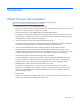
Introduction Virtual Connect documentation The following Virtual Connect documentation is available on the HP website (http://www.hp.com/go/bladesystem/documentation): • HP Virtual Connect for c-Class BladeSystem User Guide This guide provides details for the Virtual Connect GUI, including descriptions of screen contents and steps to set up domains, profiles, networks, and storage.
Setup Virtual Connect overview Virtual Connect is a set of interconnect modules and embedded software for HP BladeSystem c-Class enclosures that simplifies the setup and administration of server connections.
By stacking (cabling) the Ethernet modules within the domain and connecting the FC modules to the same set of FC SANs, every server blade in the domain can be configured to access any external network connection. With this configuration, the administrator can use Virtual Connect Manager to deploy and migrate a server blade profile to any server in the Virtual Connect domain without changing external LAN or SAN configurations.
• • Determine the Ethernet stacking cable layout, and ensure that the proper cable and transceiver options are ordered. Stacking cables allow any Ethernet NIC from any server to be connected to any of the Ethernet networks defined for the enclosure. o For information on cable layout, see "Recommended stacking connections (on page 55)." o For information on supported cable and transceiver options, see the Virtual Connect module QuickSpecs on the HP website (http://www.hp.com).
4. Connect Virtual Connect Ethernet module uplinks to data center networks. The network administrator should have already installed the network cables into the rack with the proper labels. See "Connecting Virtual Connect Ethernet module uplinks (on page 57)." 5. Connect data center FC fabric links (if applicable). 6. Note the default DNS name, user name, and password settings for the Virtual Connect Ethernet module in interconnect bay 1, available on the module Default Network Settings label. 7.
IEEE 802.3ad LACP.) All stacking links are disabled. This default configuration is to enable connectivity testing between server NICs and devices outside the enclosure prior to Virtual Connect domain configuration. Beginning with Virtual Connect Fibre Channel module firmware v1.20, when not part of a Virtual Connect domain, all of the VC-FC Module uplink ports are grouped into an uplink port group and dynamically distribute connectivity from all server blades across all available uplink ports.
Component identification HP 1/10Gb VC-Enet Module components and LEDs HP 1/10Gb VC-Enet Module components Item Description 1 Port X1 (10GBASE-CX4) 2 Port X2 (10GBASE-CX4) 3 USB 2.
HP 1/10Gb VC-Enet Module LEDs Item Description Status 1 Module locator (UID) Blue = Module ID is selected. Module status Green = Normal operation 2 Off = Module ID is not selected. Amber = Degraded condition Off = Module powered off 3 X1/X2 port status (10GBASE-CX4) Green = Port is configured and operating as an uplink port connected to a data center fabric. Amber = Port is operating as a stacking link interconnecting HP VC FlexFabric 10Gb/24-port Modules.
HP 1/10Gb VC-Enet Module system maintenance switch Switch Default Function 1 Off Off = Normal operation On = Restore factory default login and DNS information 2 Off Reserved 3 Off Reserved 4 Off Reserved HP 1/10Gb-F VC-Enet Module components and LEDs HP 1/10Gb-F VC-Enet Module components Item Description 1 Port X1 (10GBASE-CX4) 2 Port X2 XFP connector* 3 Port X3 XFP connector* Component identification 14
Item Description 4 Port S1 SFP connector** 5 Port S2 SFP connector** 6 USB 2.
Item LED description Status 6 Port X2/X3 activity Green = Link Green flashing = Activity Off = No link, unsupported or absent pluggable module 7 Port S1/S2 status Green = Port is configured and operating as an uplink port connected to a data center fabric. Amber = Port is operating as a stacking link interconnecting Virtual Connect module.
HP 1/10Gb-F VC-Enet Module system maintenance switch Switch Default Function 1 Off Off = Normal operation On = Restore factory default login and DNS information* 2 Off Reserved 3 Off Reserved 4 Off Reserved *See "Resetting the Administrator password and DNS settings (on page 33).
HP Virtual Connect Flex-10 10Gb Ethernet Module components and LEDs HP Virtual Connect Flex-10 10Gb Ethernet Module components Item Description 1 Port X1 (10GBASE-CX4), multiplexed with item 4 2 USB 2.
HP Virtual Connect Flex-10 10Gb Ethernet Module LEDs Item LED description Status 1 Module locator (UID) Blue = Module ID is selected. Module status Green = Normal operation 2 Off = Module ID is not selected. Amber = Degraded condition Amber flashing = Fault condition Off = Power off 3 X1 port status (10GBASE-CX4) Green = Port is configured and operating as an uplink port connected to a data center fabric. Amber = Port is operating as a stacking link interconnecting Virtual Connect modules.
Item LED description Status 7 X7/X8 shared port activity Green = Port is active. X7/X8 port status Green = Port is configured and operating as an uplink port connected to a data center fabric. 8 Off = Port is inactive. Amber = Port is operating as a stacking link interconnecting Virtual Connect modules. Blue = Port locator (PID) Off = Unconfigured 9 X1/X6 port status Green = Port is configured and operating as an uplink port connected to a data center fabric.
• If there is no module installed in the SFP+ port, and the port has not been configured as an uplink in a VC Ethernet network, then the corresponding internal cross-link is the active port. The LED under the SFP+ port is off. • If there is no module installed in the SFP+ port, and the port has been configured as an uplink in a VC Ethernet network, then the SFP+ port is the active port. The LED under the SFP+ port is on.
HP 4Gb Fibre Channel Module components and LEDs HP 4Gb VC-FC Module components Item Description 1 SFP 1/2/4 Gb port 1 2 SFP 1/2/4 Gb port 2 3 SFP 1/2/4 Gb port 3 4 SFP 1/2/4 Gb port 4 5 Reset button (recessed) In the default configuration (before a Virtual Connect domain is created), all 1/2/4 Gb capable uplink ports are grouped into an uplink port group and dynamically distribute connectivity from all 16 server blades.
HP 4Gb VC-FC Module LEDs Item LED description Status 1 Module locator (UID) Blue = Module ID selected Module status Green = Normal operation 2 Off = Module ID not selected Amber = Degraded condition Off = Power off 3 Port Green = Port is configured as the uplink for one or more server HBAs. Blue = Port is selected.
HP 4Gb VC-FC Module system maintenance switch Switch Default Function 1 Off Reserved 2 Off Reserved 3 Off Reserved 4 Off Reserved When part of a Virtual Connect domain, Virtual Connect Manager overrides any system maintenance switch settings.
HP Virtual Connect 4Gb FC Module (with enhanced NPIV) components and LEDs HP Virtual Connect 4Gb FC Module components Item Description 1 1/2/4 Gb capable SFP connectors Device bays supported in default configuration 1-16 (c7000) 1-8 (c3000) 2 Reset button (recessed) — In the default configuration (before a Virtual Connect domain is created), all 1/2/4 Gb capable uplink ports are grouped into an Uplink Port Group and dynamically distribute connectivity from all server blades.
HP Virtual Connect 4Gb FC Module LEDs Item LED description Status 1 Module locator (UID) Blue = Module ID selected Module status Green = Normal operation 2 Off = Module ID not selected Amber = Degraded condition Off = Power off 3 Port Green = Port is configured as the uplink for one or more server HBAs. Amber = Port is not configured. Blue = Port is selected.
HP Virtual Connect 4Gb FC Module system maintenance switch Switch Default Function 1 Off Reserved 2 Off Reserved 3 Off Reserved 4 Off Reserved When part of a Virtual Connect domain, Virtual Connect Manager overrides any system maintenance switch settings.
HP Virtual Connect 8Gb 24-Port Fibre Channel Module components and LEDs HP VC 8Gb 24-Port FC Module components Item Description Device bays supported when in default configuration 1 SFP/SFP+ ports supporting 8Gb SFP+ and 4Gb SFP transceivers 1-16 2 Reset button (recessed) — Component identification 28
HP VC 8Gb 24-Port FC Module LEDs Item LED description Status 1 Module locator (UID) Blue = Module ID selected Module status Green = Normal operation 2 Off = Module ID not selected Amber = Degraded condition Off = Power off 3 Port link/activity Green = Port is online, but not passing traffic Green slow flashing = Port is online and not logged in (NPIV not enabled or supported on external devices) Green flickering = Port is online passing traffic Amber = Port has light or signal, but not yet onli
HP VC 8Gb 24-Port FC Module system maintenance switch Switch Default Function 1 Off Reserved (must be in "Off" position) 2 Off Reserved (must be in "Off" position) 3 Off Reserved (must be in "Off" position) 4 Off Off = Module debug and test interface is inaccessible. On = Module debug and test interface is accessible. When part of a Virtual Connect domain, Virtual Connect Manager overrides any system maintenance switch settings.
HP Virtual Connect 8Gb 20-Port Fibre Channel Module components and LEDs HP VC 8Gb 20-Port FC Module components Item Description 1 SFP/SFP+ ports supporting 8Gb SFP+ and 4Gb SFP transceivers 1-8 (c3000) Reset button (recessed) — 2 Device bays supported in default configuration 1-16 (c7000) In the default configuration, before a Virtual Connect domain is created, all uplink ports are grouped into an uplink port group and dynamically distribute connectivity from all server blades.
Item LED description Status 1 Module locator (UID) Blue = Module ID is selected. Module status Green = Normal operation 2 Off = Module ID is not selected. Amber = Degraded condition Off = Power off 3 Logged in Green = Logged in to an external Fibre Channel switch port Off = Port down, offline, no sync, or error 4 Activity Green flashing (variable) = Link activity Green flashing (1 Hz) = External fabric switch does not support NPIV.
Switch Default Function 4 Off Reserved When part of a Virtual Connect domain, Virtual Connect Manager overrides any system maintenance switch settings.
13. Insert the Virtual Connect Ethernet module into interconnect bay 1 and allow the module to power up and reach a fully booted and operation state (approximately 1 minute). 14. Log into the VC Manager using the factory default user name and password to log in to the module (regardless of whether it is running on the module in interconnect bay 1 or interconnect bay 2). 15. Change the Administrator password.
Installation Supported configurations The following table outlines the Ethernet, Fibre Channel, and enclosure support for each version of Virtual Connect. VC firmware version Enclosure Ethernet support FC support Enclosures per single VC domain 1.10 c3000 — — — 1.10 and higher c7000 Up to 8 modules Up to 4 modules 1 1.20 and higher c3000 Up to 4 modules Up to 2 modules 1 2.10 and higher c7000 Up to 16 modules Up to 16 modules Up to 4 2.
• For c3000 enclosures, VC-FC modules are not supported in interconnect bay 2. IMPORTANT: To support high availability, always install Virtual Connect Ethernet modules in interconnect bays 1 and 2. Multiple enclosure support Virtual Connect version 2.10 and higher supports the connection of up to four c7000 enclosures, which can reduce the number of network connections per rack and also enables a single VC manager to control multiple enclosures.
[Bay 7] Other/empty [Bay 8] Other/empty [Bay 1] VC Ethernet [Bay 2] VC Ethernet [Bay 3] VC-FC [Bay 4] VC-FC [Bay 5] Other/empty [Bay 6] Other/empty [Bay 7] Other/empty [Bay 8] Other/empty [Bay 1] VC Ethernet [Bay 2] VC Ethernet [Bay 3] VC Ethernet [Bay 4] VC Ethernet [Bay 5] VC-FC [Bay 6] VC-FC [Bay 7] Empty [Bay 8] Empty [Bay 1] VC Ethernet * [Bay 2] VC Ethernet [Bay 3] VC Ethernet [Bay 4] VC Ethernet [Bay 5] VC-FC [Bay 6] VC-FC [Bay 7] VC-FC [Bay 8] VC-FC
HP BladeSystem c3000 Enclosure supported configurations The following tables show a number of typical, supported configurations for an HP BladeSystem c3000 Enclosure.
• VC-FC module SFP ports can be connected only to Fibre Channel switch ports that support N_port_ID virtualization. To verify that NPIV support is provided, see the firmware documentation that ships with the Fibre Channel switch. • Install the VC-FC modules in interconnect bays 3 or higher. Interconnect bays 1 and 2 are reserved for Ethernet modules. • All modules in the enclosure require a valid and unique IP address, and all modules must be on the same subnet.
Firmware requirements IMPORTANT: HP recommends that each type of VC module in the domain use the same VC firmware revision level. Some versions of the Virtual Connect firmware might not be compatible. The active Virtual Connect Manager does not allow incompatible modules to be managed as part of the Virtual Connect domain. IMPORTANT: For optimal operation of HP Virtual Connect, use the recommended firmware versions.
All enclosure OAs and VC modules within the same VC domain must be on the same lightly loaded subnet. The OA IP addresses used must be configured to be static. The VC-Enet modules use stacking cables between enclosures to route network traffic from any server port to any uplink port within the VC domain. Bay 1 and bay 2 of the primary enclosure must have Fibre uplinks. IMPORTANT: In multi-enclosure configurations, the HP 1/10 Gb VC-Enet Module is not supported in bay 1 or bay 2 of the primary enclosure.
• All enclosures must have the same FC module configuration. • A single domain supports up to four c7000 enclosures. • For c7000 enclosures, install up to 16 VC-Enet modules and up to 16 VC-FC modules in the same domain, with a maximum of 8 VC-Enet or 4 VC-FC modules per enclosure. • All VC-Enet modules must be interconnected (stacked). • All OAs and VC modules must be on the same management Ethernet network and IP subnet. • VC modules must be running Virtual Connect version 2.10 or higher.
Bay 3 Bay 4 Good configuration? Notes 4Gb FC 4Gb FC with enhanced NPIV Yes You can mix HP 4Gb VC-FC modules and HP Virtual Connect 4Gb FC modules (with enhanced NPIV) in horizontally adjacent bays. 4Gb FC 8Gb 24-Port FC No Do not mix 4Gb FC and 8Gb 24-Port FC modules in horizontally adjacent bays. 4Gb FC 8Gb 20-Port FC Yes You can mix HP VC 4Gb VC-FC modules and HP 8Gb 20-Port FC modules in horizontally adjacent bays.
For example, in a multi-enclosure domain with a total of four enclosures, if bays 3 and 4 of the Primary Enclosure contain VC-FC modules, then bays 3 and 4 of Remote Enclosures 1, 2, and 3 must also contain VC-FC modules. The following illustration shows a valid FC bay configuration.
The following illustration shows an invalid FC bay configuration. Bay 4 in Remote Enclosure 1 is empty, and Bay 3 of Remote Enclosure 2 has an Ethernet module present. Directly connecting VC domains In a multi-enclosure domain configuration with properly installed stacking cables, each network defined in the domain is available to all server profiles in the domain without requiring any additional uplink ports.
Module removal and replacement Beginning with VC v3.00, it is no longer necessary to administratively remove a module if the module is not in use. If a module is not in use and is physically removed, it is automatically removed from the domain. However, if you are removing a module that is in interconnect bay 1 or bay 2 of the primary enclosure, you must first delete the domain, and then recreate it after the module has been removed.
2. Prepare the VC-Enet module for installation (HP VC Flex-10 10Gb Ethernet Module shown). 3. Install the module into the interconnect bay (HP VC Flex-10 10Gb Ethernet Module shown). Push the module in slowly and smoothly until firmly seated. 4. If the VC Manager configuration includes three or more VC-Enet modules, install stacking links (typically 10GBASE-CX4 cables) between the modules. For more information, see "Connecting Virtual Connect Ethernet Module uplinks (on page 57)." 5.
IMPORTANT: For proper thermal operation, always install SFP dust covers in SFP ports without SFP transceivers installed. 6. Remove the perforated portion of the Default Network Setting label that extends beyond the faceplate of the VC-Enet module installed in interconnect bay 1, or record the information contained on the label. The Default Network Settings label contains the DNS name, user name, and password of the interconnect module in interconnect bay 1.
profiles, see the HP Virtual Connect for c-Class BladeSystem User Guide on the HP website (http://www.hp.com/go/bladesystem/documentation). Upgrading to an HP Virtual Connect Flex-10 Module Upgrading an enclosure to Flex-10 support requires several steps, depending on the starting configuration. Replacing a Virtual Connect Ethernet Module with an HP Virtual Connect Flex-10 Module in bays 3 to 8 1. Upgrade the VC domain firmware to v2.01 or higher. 2. Save the configuration. 3.
Installing a VC-FC module 1. Remove the interconnect blank. NOTE: HP Virtual Connect works optimally in enclosures configured with HP Virtual Connect interconnect modules only. 2. Prepare the VC-FC module for installation (HP Virtual Connect 4Gb Fibre Channel Module shown).
3. Install the VC-FC module into the interconnect bay (HP Virtual Connect 4Gb Fibre Channel Module shown). Push the module in slowly and smoothly until firmly seated. 4. Connect the data center SAN switch ports to the VC-FC module 1/2/4 Gb SFP ports. IMPORTANT: For proper thermal operation, always install SFP dust covers in SFP ports without SFP transceivers installed. IMPORTANT: For proper Virtual Connect operation, always assign an IP address to each server blade iLO and interconnect module. 5.
4. Remove any FC profile connections that are connected to the interconnect bays being upgraded. This can be done by un-assigning the profile (recommended) or by deleting the connections from the profile. 5. If there are any FC SAN fabrics that were created using uplinks from the interconnect bays being upgraded, delete these FC SAN Fabrics from the Virtual Connect domain. 6. Physically remove the existing modules from BOTH horizontally adjacent bays. 7.
5. If there are any FC SAN fabrics that were created using uplinks from the interconnect bays being upgraded, delete these FC SAN Fabrics from the Virtual Connect domain. 6. Physically remove the existing modules from BOTH horizontally adjacent bays 7. When the above conditions are met, administratively remove the modules from Virtual Connect domain. 8. Install the HP VC 8Gb 20-port FC Modules. 9. Re-create previously deleted FC SAN fabrics. 10.
Ensure that the latch is closed and that the transceiver is fully seated. 3. Do one of the following: o Connect the appropriate cable. o Install the dust plug onto the transceiver. Removing SFP/SFP+/XFP transceivers WARNING: To avoid serious injury, never look directly into an open transceiver port. CAUTION: Disconnect all cables before removing or installing an SFP/SFP+/XFP transceiver, because of the potential damage to the cables, the cable connector, or the optical interfaces in the transceiver.
3. Remove the transceiver. (SFP transceiver shown). 4. Install dust plugs on the fiber-optic transceiver and rubber plugs on the fiber-optic cable. CAUTION: Be sure to install the dust plugs on the fiber-optic transceiver and the rubber plugs on the fiber-optic cable. The plugs and caps protect the transceiver ports and cables from contamination and ambient light.
Virtual Connect Ethernet modules support 10GBASE-CX4 stacking cables 0.5 m to 7 m (1.64 ft to 23.00 ft). The 1000BASE-T links can also be used as stacking links of up to 100 m (328 ft). Ports with different connector types can be aggregated if the link speed is the same. For example, CX4 and SFP+ ports both running at 10G can be aggregated to provide enhanced throughput for the stacking link.
Factory default settings The Virtual Connect Delete Domain operation returns all VC-FC modules to the factory default settings. VC-FC modules that are physically removed from a VC domain can be returned to the factory default settings when placed into a new enclosure by applying power, and then pressing and holding the reset button on the front panel for at least 10 seconds.
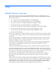
The following sections provide an overview of the types of external connections and their behaviors. Mapping individual networks to individual external uplink ports The simplest approach to connecting the defined networks to the data center is to map each network to a specific external uplink port.
• When multiple external uplink ports are used for the same network, the Virtual Connect Ethernet modules provide automatic loop prevention by allowing for a single active link or link set at any one time. • The Virtual Connect system automatically chooses the uplink (ports) that optimize throughput and availability. Where possible, links within the uplink port set automatically form a link aggregation group using LACP.
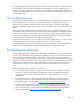
Network Shared uplink port and VLAN Production_Network Shared_Uplink_Port_A:VLAN_15 Dev_Network Shared_Uplink_Port_A:VLAN_21 Backup_Network Shared_Uplink_Port_A:VLAN_32 iSCSI_Storage_Network Shared_Uplink_Port_A:VLAN_76 Because appropriate VLAN tags are added as the packets leave the enclosure, this type of uplink should not be used in cases where VLAN tags are already added on the server itself.
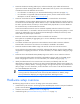
In the following example, LACP is used on the Cisco Switch to connect to a shared uplink set using three uplink ports. VLANs 10, 20, 30, and 40 from the network are tagged on the three shared uplink ports. IMPORTANT: Change Channel Mode to LACP on the Cisco switch. By default, all ports on a Catalyst 4500/4000 switch and a Catalyst 6500/6000 switch use channel protocol PAgP and as such are not running LACP. For all ports concerned, you must change the channel mode to LACP.
switchport switchport trunk encapsulation dot1q switchport trunk allowed vlan 10,20,30,40 switchport mode trunk no ip address interface GigabitEthernet7/46 description test-VC switchport switchport trunk encapsulation dot1q switchport trunk allowed vlan 10,20,30,40 switchport mode trunk no ip address speed 1000 channel-protocol lacp channel-group 10 mode active ! interface GigabitEthernet7/47 description test-VC switchport switchport trunk encapsulation dot1q switchport trunk allowed vlan 10,20,30,40 switch
NOTE: HP recommends saving a configuration after each session and before updating firmware.
HP Virtual Connect Manager Configuring browser support Access to the application must be through HTTPS (HTTP exchanged over an SSL-encrypted session). For optimal viewing, HP recommends setting the screen resolution to 1280 x 1024. Requirements The HP Virtual Connect Manager Web interface requires an XSLT-enabled browser with support for JavaScript 1.3 or equivalent. The following browsers are supported: • Microsoft® Internet Explorer 7.x or higher • Mozilla Firefox 3.
Always apply relevant licenses that are dependent on MAC addresses after the server profiles are assigned so that the licenses are not lost due to a change in MAC address. IMPORTANT: If you plan to use RDP for RedHat Linux installation and also plan to use Useror HP-defined MAC addresses, you must import the enclosure before running RDP. RDP "rip and replace" is not supported in a Virtual Connect environment.
Command line overview The HP Virtual Connect Manager Command Line Interface can be used as an alternative method for managing the Virtual Connect Manager. Using the CLI can be useful in the following scenarios: • HP Management Applications (for example, Systems Insight Manager or Insight Control tools) can query the Virtual Connect Manager for information these tools need to present a complete management view of HP BladeSystem enclosures and devices.
• There is no connection to the Virtual Connect Ethernet module running the active Virtual Connect Manager. • The Virtual Connect Manager is in the middle of a failover or recovery. • The attempted IP sign-in address is not valid for the specified account. • The attempted IP sign-in address is for a Virtual Connect Ethernet module not running the active Virtual Connect Manager. • The browser settings are incorrect. See "Configuring browser support (on page 64).
Reset Virtual Connect Manager Users must have Administrative privileges to reset the Virtual Connect Manager. In a multi-enclosure environment, the Ethernet modules in bays 1 and 2 of the primary enclosure host the Virtual Connect Manager. To reset the Virtual Connect Manager application running on the primary Virtual Connect Ethernet module, select Reset Virtual Connect Manager from the Tools pull-down menu. The Reset Virtual Connect Manager screen is displayed.
• • Note the following information from the Default Network Settings label attached to the primary module: o DNS name o User name o Password Connect any Ethernet module stacking cables ("Recommended stacking connections" on page 55). After logging in for the first time, the Virtual Connect Domain Setup Wizard appears.
Enter the user name and password for the enclosure Onboard Administrator. The local enclosure is detected and selected automatically. If an error appears, it indicates that an invalid Onboard Administrator user name and password, or one without sufficient privileges, might have been used. After you import the remote enclosure, the OA IP address must not change. You must always assign a static IP address or configure it appropriately through your DHCP server.
• To create the Virtual Connect domain by importing an enclosure, select the 'Create a new Virtual Connect domain by importing this enclosure' radio button, and then click Next. This process can take several minutes as the Virtual Connect Manager establishes contact with each module in the enclosure and identifies its capabilities.
Enclosure Import After making the selection to create a new Virtual Connect domain by importing the enclosure on the Enclosure Import/Recovery screen, the Import Status screen appears and provides information about whether the import was successful. If the import is not successful, error information is displayed. Importing additional enclosures To import additional enclosures using the Domain Setup Wizard after the initial enclosure has been imported: 1. Select Tools -> Domain Setup Wizard. 2.
Using double-dense server blades Beginning with version 1.31, Virtual Connect Manager supports the use of double density server blades, which means support for up to 32 device bays in a single c7000 enclosure. This support also provides 32 new device bays (1A-16A and 1B-16B) for profile assignment. On a c3000 enclosure, this feature supports 8 additional or 16 total device bays. (1A-8A and 1B-8B.
General Settings The Virtual Connect domain name must be unique within the data center, and can be up to 64 characters without spaces or special characters. The Domain Setup Wizard automatically assigns a domain name (enclosurename_vc_domain). This name can be changed when running the setup wizard, or at anytime from the "Domain Settings (Domain Configuration) screen.
Local Users The first time this page appears, the only local user account is the Administrator account, which has domain privileges. The Administrator account cannot be deleted or have domain privileges removed. The Administrator password can be changed. The default Administrator password is identified on the Default Network Settings label on the VC-Enet module in bay 1 of the enclosure.
• To enable strong passwords or enable local users, click Advanced. To enable the use of strong passwords, select the 'Require Strong Passwords' checkbox. Use the up and down arrows to select a password length between 3 and 40 characters.
User Settings Observe the following user settings guidelines: • Username is a required field. • A username must contain an alpha-numeric value with 1 to 13 characters. • A password must contain an alpha-numeric value with 3 to 40 characters.
• • • o Administer SSL certificates o Delete the VC domain o Save configuration to disk o Restore the configuration from a backup o Configure SNMP settings Networking o Configure network default settings o Select the MAC address range to be used by the VC domain o Create, delete, and edit networks o Create, delete, and edit shared uplink sets o Configure Ethernet SNMP settings Server o Create, delete, and edit server Virtual Connect profiles o Assign and unassign profiles to device
Finish domain wizard Click Finish to complete this wizard, and then run the Network Setup Wizard ("HP Virtual Connect Network Setup Wizard" on page 79) to define the Ethernet networks that will be available within the Virtual Connect domain. Deselect the Start the Network Setup Wizard checkbox, and then click Finish to go to the Home page.
For additional information, see “Supported configurations" and “Recommended stacking connections (on page 55)." NOTE: Virtual Connect does not support stacking for FC modules, so each VC-FC module requires uplink connections to the external FC SAN environment. To initiate this wizard, click the Network Setup Wizard link on the homepage, or select Network Setup Wizard from the Tools pull-down menu.
accessing the physical NICs through the enclosure Onboard Administrator and the iLO interfaces on the individual server blades. Always establish control processes to ensure that a unique MAC address range is used in each Virtual Connect domain in the environment. Reusing address ranges could result in server network outages caused by multiple servers having the same MAC addresses.
Select the type and range of MAC address, and then click Next. Selecting VC-assigned MAC address ranges When using VC-assigned MAC addresses, you can choose between using an HP pre-defined MAC address range or using a user-defined MAC address range. • HP pre-defined MAC address range (recommended). These pre-defined ranges are reserved and will never show up as factory default on any hardware. There are 64 ranges of 1024 unique addresses to choose from.
Server VLAN Tagging Support This option provides explicit VLAN tagging support for server links, enabling each server link to be shared among multiple networks. Users can map server VLAN-tagged Ethernet packets to specific networks, which is essential in deploying server virtualization applications such as a virtual operating system solution.
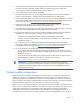
The following figure shows tunneled VLAN tags. On the dedicated, green network, both uplink and server VLAN tags are tunneled through Virtual Connect unchanged. On the shared, red and blue networks, uplink VLAN tags are mapped to networks. Untagged frames are mapped to the native VLAN, if present, otherwise they are dropped. Server frames are untagged only, and tagged frames are dropped. Each server port is connected to a single network.
possibility of configurations where server VLANs might not match external VLANs used on uplinks. To avoid this scenario, you can select the 'Force server connections to use the same VLAN mappings as shared uplink sets' option. Server port connections to networks are defined on the Define Server Profile screen. When using mapped VLAN tags (multiple networks over a single link), these settings are used for the overall link speed control. Select the checkbox next to each item to set the value.
To determine the types of network connections to use, see "Connecting Virtual Connect Ethernet module uplinks (on page 57).
To define a network: 1. Enter a name for the network that will be easily understood and recognized by the server administrators defining and deploying server profiles. The network name can be up to 64 characters in length (no spaces). 2. To enable Smart Link, select the box under Smart Link. The checkbox is not available until an uplink is added to the network. 3. To designate as a private network, select the box under Private Network. 4.
For more information on multiple networks link speed settings, see the HP Virtual Connect for c-Class BladeSystem User Guide.
Define Shared Uplink Port Set To define multiple networks that share a common set of external uplink ports: 1. Enter an overall name for the set of shared uplinks (up to 64 characters, no spaces). 2. From the Add Port drop-down menu, select the external uplink ports that will carry these networks. To delete a port, click the X in the Delete column of the row to delete. 3. Click Add Network to define the name and VLAN identifier of each network to use these shared uplinks. 4.
For more information on defining a new shared uplink set and VLAN tagging, see the HP Virtual Connect for c-Class BladeSystem User Guide. Finish network wizard When the Network Setup Wizard completes, external Fibre Channel connectivity can be configured (if applicable) or server profiles can be defined and associated with server blades. To establish external Fibre Channel connectivity: 1. Be sure the Start the Fibre Channel Wizard checkbox is selected. 2. Click Finish.
HP Virtual Connect Fibre Channel Setup Wizard This wizard configures external Fibre Channel connectivity for the HP BladeSystem c-Class enclosure using HP Virtual Connect. A user account with storage privileges is required to perform these operations. Use this wizard to do the following: • Identify WWNs to be used on the server blades deployed within this Virtual Connect domain. • Define fabrics.
Configuring Virtual Connect to assign WWNs in server blades maintains a consistent storage identity (WWN) even when the underlying server hardware is changed. This method allows server blades to be replaced without affecting the external Fibre Channel SAN administration.
Assigned WWNs The WWN range used by the Virtual Connect domain must be unique within the environment. HP provides a set of pre-defined ranges that are reserved for use by Virtual Connect and do not conflict with server factory default WWNs. When using the HP-defined WWN ranges, be sure that each range is used only once within the environment. Select the type and range of WWNs, and then click Next.
Define Fabric To define a fabric, select the Define Fabric checkbox, and then click Apply. If you do not want to define a fabric at this time, select the I do not want to create SAN Fabrics at this time checkbox, and then click Apply.
Define SAN Fabric The following actions are available on this screen: • Name the fabric. • Select the uplink port speed. • Select the uplink port(s) to be used. Only uplinks on the same bay can be in the same SAN fabric. When finished, click Apply.
Finish Fibre Channel wizard When the Fibre Channel Setup Wizard completes, server profiles can be defined and associated with server blades. Select Define Server Profiles on the home page. The FC SAN configuration can be changed at any time by using one of the following methods: • Click WWN Settings under Fibre Channel Settings int he left window of the homepage. • Select Fibre Channel Settings from the Configure pull-down menu.
2. Verify that all Virtual Connect Fibre Channel modules are powered on and functioning properly. The module status LED should be green for all modules connected and configured in Virtual Connect for data center use. If the LED is not green, use the HP Onboard Administrator user interface to diagnose the problem and verify that the module is powered on. 3. Verify that the data center switches are powered on. 4.
Regulatory compliance notices Regulatory compliance identification numbers For the purpose of regulatory compliance certifications and identification, this product has been assigned a unique regulatory model number. The regulatory model number can be found on the product nameplate label, along with all required approval markings and information. When requesting compliance information for this product, always refer to this regulatory model number.
to radio communications. However, there is no guarantee that interference will not occur in a particular installation. If this equipment does cause harmful interference to radio or television reception, which can be determined by turning the equipment off and on, the user is encouraged to try to correct the interference by one or more of the following measures: • Reorient or relocate the receiving antenna. • Increase the separation between the equipment and receiver.
Canadian notice (Avis Canadien) Class A equipment This Class A digital apparatus meets all requirements of the Canadian Interference-Causing Equipment Regulations. Cet appareil numérique de la classe A respecte toutes les exigences du Règlement sur le matériel brouilleur du Canada. Class B equipment This Class B digital apparatus meets all requirements of the Canadian Interference-Causing Equipment Regulations.
Disposal of waste equipment by users in private households in the European Union This symbol on the product or on its packaging indicates that this product must not be disposed of with your other household waste. Instead, it is your responsibility to dispose of your waste equipment by handing it over to a designated collection point for the recycling of waste electrical and electronic equipment.
Korean notice Class A equipment Class B equipment Chinese notice Class A equipment Laser compliance This product may be provided with an optical storage device (that is, CD or DVD drive) and/or fiber optic transceiver. Each of these devices contains a laser that is classified as a Class 1 Laser Product in accordance with US FDA regulations and the IEC 60825-1. The product does not emit hazardous laser radiation. Each laser product complies with 21 CFR 1040.10 and 1040.
Electrostatic discharge Preventing electrostatic discharge To prevent damaging the system, be aware of the precautions you need to follow when setting up the system or handling parts. A discharge of static electricity from a finger or other conductor may damage system boards or other static-sensitive devices. This type of damage may reduce the life expectancy of the device. To prevent electrostatic damage: • Avoid hand contact by transporting and storing products in static-safe containers.
Technical support Before you contact HP Be sure to have the following information available before you call HP: • Technical support registration number (if applicable) • Product serial number • Product model name and number • Product identification number • Applicable error messages • Add-on boards or hardware • Third-party hardware or software • Operating system type and revision level HP contact information For the name of the nearest HP authorized reseller: • See the Contact HP worldwi
• Optional—Parts for which customer self repair is optional. These parts are also designed for customer self repair. If, however, you require that HP replace them for you, there may or may not be additional charges, depending on the type of warranty service designated for your product. NOTE: Some HP parts are not designed for customer self repair. In order to satisfy the customer warranty, HP requires that an authorized service provider replace the part.
Pour plus d'informations sur le programme CSR de HP, contactez votre Mainteneur Agrée local. Pour plus d'informations sur ce programme en Amérique du Nord, consultez le site Web HP (http://www.hp.com/go/selfrepair). Riparazione da parte del cliente Per abbreviare i tempi di riparazione e garantire una maggiore flessibilità nella sostituzione di parti difettose, i prodotti HP sono realizzati con numerosi componenti che possono essere riparati direttamente dal cliente (CSR, Customer Self Repair).
HINWEIS: Einige Teile sind nicht für Customer Self Repair ausgelegt. Um den Garantieanspruch des Kunden zu erfüllen, muss das Teil von einem HP Servicepartner ersetzt werden. Im illustrierten Teilekatalog sind diese Teile mit „No“ bzw. „Nein“ gekennzeichnet. CSR-Teile werden abhängig von der Verfügbarkeit und vom Lieferziel am folgenden Geschäftstag geliefert. Für bestimmte Standorte ist eine Lieferung am selben Tag oder innerhalb von vier Stunden gegen einen Aufpreis verfügbar.
el caso de todas sustituciones que lleve a cabo el cliente, HP se hará cargo de todos los gastos de envío y devolución de componentes y escogerá la empresa de transporte que se utilice para dicho servicio. Para obtener más información acerca del programa de Reparaciones del propio cliente de HP, póngase en contacto con su proveedor de servicios local. Si está interesado en el programa para Norteamérica, visite la página web de HP siguiente (http://www.hp.com/go/selfrepair).
Opcional – Peças cujo reparo feito pelo cliente é opcional. Essas peças também são projetadas para o reparo feito pelo cliente. No entanto, se desejar que a HP as substitua, pode haver ou não a cobrança de taxa adicional, dependendo do tipo de serviço de garantia destinado ao produto. OBSERVAÇÃO: Algumas peças da HP não são projetadas para o reparo feito pelo cliente. A fim de cumprir a garantia do cliente, a HP exige que um técnico autorizado substitua a peça.
Technical support 110
Technical support 111
Acronyms and abbreviations BPDU Bridge Protocol Data Unit DHCP Dynamic Host Configuration Protocol DNS domain name system EBIPA Enclosure Bay IP Addressing FC Fibre Channel HBA host bus adapter iSCSI Internet Small Computer System Interface LACP Link Aggregation Control Protocol LAG link aggregation group LLDP Link Layer Discovery Protocol MAC Media Access Control NPIV N_Port ID Virtualization Acronyms and abbreviations 112
OA Onboard Administrator POST Power-On Self Test RDP Rapid Deployment Pack SFP small form-factor pluggable SSL Secure Sockets Layer USB universal serial bus VLAN virtual local-area network WWN World Wide Name XFP 10 Gb small form factor pluggable Acronyms and abbreviations 113
Index A About menu 67 accessing HP Virtual Connect Manager 9, 65 ActiveX 64 adding enclosures 72 Advanced Network Settings 87 allowing double density device bays 70 assigned MAC addresses 80 assigned WWNs 93 authorized reseller 104 B browser requirements 64, 65 BSMI notice 101 buttons 12 C cables 99 cabling 55, 57 Canadian notice 100 check-pointing 62 Chinese notice 102 Cisco Core switch 60 class A equipment 98 class B equipment 98 CLI (Command Line Interface) 66 command line interface, using 66 command l
Fibre Channel settings (WWN) 91 finish wizard 79, 90, 96 firmware requirements 40 Flex-10 installation guidelines 39 G general settings 74 grounding methods 103 H hardware setup 9, 46, 50 help resources 104 high availability support 62 homepage, Virtual Connect Manager 67 HP 1/10Gb VC-Enet Module 14 HP 1/10Gb-F VC-Enet Module 17 HP 4Gb Fibre Channel Module components and LEDs 22 HP 4Gb VC-FC Module 24 HP technical support 104 HP Virtual Connect 4Gb FC Module 27 HP Virtual Connect 4Gb FC Module (with enhan
P password, resetting 33 phone numbers 104 port WWN 91 pre-deployment planning 8 private networks 86 R RDP, using with Virtual Connect 64 recommended stacking connections 55 recovering remote enclosures 68 recovery, enclosure 73 Red Hat procedures 64 redundant configuration 55 regulatory compliance identification numbers 98 regulatory compliance notices 98, 101 remote enclosures, recovering 68 resetting the adminsitrator password 33 resetting the system 68 running the setup wizards 68 S series number 98 S