
HP Virtual Connect for c-Class BladeSystem Version 3.00 Setup and Installation Guide for HP Integrity BL8x0c i2 Series Server Blades

Installation 58
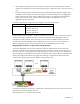
The following sections provide an overview of the types of external connections and their behaviors.
Mapping individual networks to individual external uplink ports
The simplest approach to connecting the defined networks to the data center is to map each network to a
specific external uplink port. This uplink port is defined by the following:
• Enclosure name
• Interconnect bay containing the Virtual Connect Ethernet module
• Selected port on that module
Port status indicators can be used to locate a specific port or to provide additional status.
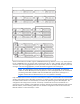
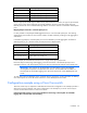
The following table shows an example of simple network mapping, where the Virtual Connect enclosure is
named Enclosure1 and Virtual Connect Ethernet modules are in interconnect module bays 1 and 2.
Network Uplink port
Production_Network Enclosure1:Bay1:PortX2
Dev_Network Enclosure1:Bay1:Port4
Backup_Network Enclosure1:Bay2:Port3
iSCSI_Storage_Network Enclosure1:Bay2:PortX2
In this case, the Ethernet packets are passed unchanged between the server blades and the external
networks. Any VLAN tags added by the server or external switch are ignored and pass through the Virtual
Connect Ethernet modules.
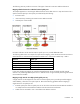
Mapping a single network to multiple uplinks (uplink port set)
A single network can be mapped to more than one external uplink port to provide improved throughput
and availability, referred to as an uplink port set. Review the following guidelines before mapping a
single network to an uplink port set:
• External uplink ports within an uplink port set can be on the same Virtual Connect Ethernet module or
on multiple Virtual Connect Ethernet modules within the Virtual Connect domain.
• Cables can be connected to one or more data center Ethernet switches.