
HP Virtual Connect Multi-Enclosure Stacking Reference Guide

18
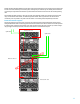
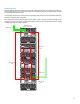
It is customary to put uplink cables on the top-most and bottom-most enclosures as shown in most of the example
pictures above. You can also put uplink cables on the first and second enclosures as shown in the 3-enclosure example
picture. This has one advantage when you are also running VCEM in the environment: this 3-enclosure domain could
coexist in a VCEM domain group with a 2-enclosure domain precisely because the 3
rd
enclosure does not have any
Ethernet uplink, which makes VCEM consider this enclosure as “optional” in the domain group configuration.
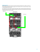
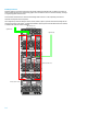
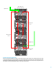
You can also put uplinks on more than 2 enclosures, however remember that one of the main benefits of multi-
enclosure stacking is to save on the number of uplink cables and ports.
Consolidating Existing VC Domains and Enclosures
This section will outline an example to consolidate multiple independent VC Domains into a ME Stack with one VC
domain.
This configuration is more complex as you will be dealing with existing VC domains, VC network uplinks and host
configurations. This configuration will need to have some scheduled downtime allotted to make the required changes to
the Virtual Connect infrastructure.
Important: ME Stacking will not support “merging” of existing VC domains, remote
enclosure VC domains must be deleted in order for stacking to be successful.
Enclosures being imported must have no previous Virtual Connect domains configured. The Base enclosure becomes the
only VC domain for the entire ME Stack.
This is an example set of steps for ‘importing’ a previously configured remote Virtual Connect domain and what you have
to plan for.
Backup ALL VC domains
Create a VC CLI script to recreate the Profiles for all the blades in the remote enclosures: do not assign them to
server bays at this time. The new profile MAC and WWPN’s will be created with the HP Predefined managed
range of the base enclosure. If you are using Virtual Connect firmware 3.30 or later, you can use the CLI
command “show config” to create a script that can be edited and used to recreate these profiles.
Decide on new stack uplink port strategy – will all the existing uplink ports be used in the new stacked domain
or will additional be added?
Decide on new naming convention for remote enclosure VC network uplink ports (if the same name as the base
enclosure)
Import the remote enclosures through the CLI or GUI interface.
Take the new WWPN’s created in the new unassigned profiles and have them zoned and presented in parallel
with the existing WWPN’s for storage. Once the enclosures are stacked and the new profiles assigned to the
remote servers, remove the old WWPN’s from the storage infrastructure.
If Needed – Create a CLI script to define new VC Networks using the remote enclosure uplink ports.
Create a CLI script to assign the new profiles to the correct blade server bays.
Removing an enclosure from a multi-enclosure domain
You can remove an enclosure from a multi-enclosure domain as long as it is not the base enclosure with the VC modules
that manage the domain. In order to do so, you must first unassign or move all the server profiles that were assigned to
server bays in the enclosure you want to remove. You must also make sure that no network, shared uplink set or port
monitor use any uplink port on the VC modules in that enclosure. You can then go to Domain Settings in Virtual Connect
Manager and click Delete in the Action column of the row displaying the enclosure you want to remove from the domain.
You can also select the enclosure you want to remove, right-click and choose delete from the pop-up menu. After the
enclosure is removed, its Virtual Connect modules will be back to unconfigured mode and you will have to create another
VC domain in that enclosure (or import it into another multi-enclosure domain). This operation has no effect on the base
enclosure or the other remote enclosures of the domain, they will remain up and running normally.