
HP Virtual Connect Fibre Channel Networking Scenarios Cookbook

27
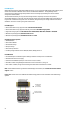
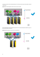
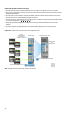
Physical view of a Direct-Attach Flat SAN configuration
Figure 27: Virtual Connect Flat SAN with VC FlexFabric modules for HP 3PAR Storage Systems,
Redundant paths - Server-to- Direct-Attach uplink ratio 16:1
Enclosure
UID
Enclosure Interlink
PS
3
PS
2
PS
1
PS
6
PS
5
PS
4
OA1 OA2
Remove management modules before ejecting sleeve
FAN
6
FAN
10
FAN
1
FAN
5
2
1
3
5
7
4
6
8
iLO
UID
Active
Reset
iLO
UID
Active
Reset
HP V C F le xFa br ic 10 Gb /2 4-P or t Mod ul e
SHAR ED : U PL IN K o r X -L I NK
X3 X4X1 X2 X5 X6 X7 X8
UID
HP V C F le xFa br ic 10 Gb /2 4-P or t Mod ul e
SHAR ED : U PL IN K o r X -L I NK
X3 X4X1 X2 X5 X6 X7 X8
UID
Console Unit
5 6 15 1613 1411 129 107 81 2 3 4 21 22 31 3229 3027 2825 2623 2417 18 19 20 37 38 47 4845 4643 4441 4239 4033 34 35 36
Series
100%
80%
60%
40%
20%
49 525150
RPS
PWR
10/100Base-TX 1000Base-X
H3C S 360 0
Speed:Green=100Mbps,Yellow=10Mbps
Duplex:Green=Full Duplex,Yellow=Half Duplex Power:Green=DeliveringPower,Yellow=Fault,Flashing Green=Over Budget
Green=Speed
Mode
Yellow=Duplex
Flashing=PoE
LAN Switch A
LAN Switch B
SUS-1
SUS-2
Ethernet uplink
connection
Console Unit
5 6 15 1613 1411 129 107 81 2 3 4 21 22 31 3229 3027 2825 2623 2417 18 19 20 37 38 47 4845 4643 4441 4239 4033 34 35 36
Series
100%
80%
60%
40%
20%
49 525150
RPS
PWR
10/100Base-TX 1000Base-X
H3C S 360 0
Speed:Green=100Mbps,Yellow=10Mbps
Duplex:Green=Full Duplex,Yellow=Half Duplex Power:Green=DeliveringPower,Yellow=Fault,Flashing Green=Over Budget
Green=Speed
Mode
Yellow=Duplex
Flashing=PoE
Ethernet uplink
connection
HP BladeSystem c7000
HP 3PAR StoreServ 10400
SAN uplink
connections
(Direct-Attach)
Controller Node 0
Controller Node 1
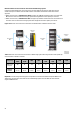
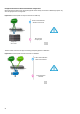
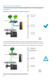
Figure 28: Virtual Connect Flat SAN with VC FlexFabric modules for HP 3PAR Storage Systems,
Redundant paths - Server-to- Direct-Attach uplink ratio 8:1
Enclosure
UID
Enclosure Interlink
PS
3
PS
2
PS
1
PS
6
PS
5
PS
4
OA1 OA2
Remove management modules before ejecting sleeve
FAN
6
FAN
10
FAN
1
FAN
5
2
1
3
5
7
4
6
8
iLO
UID
Active
Reset
iLO
UID
Active
Reset
HP V C F le xFa br ic 10 Gb /2 4-P or t Mod ul e
SHAR ED : U PL IN K o r X -L I NK
X3 X4X1 X2 X5 X6 X7 X8
UID
HP V C F le xFa br ic 10 Gb /2 4-P or t Mod ul e
SHAR ED : U PL IN K o r X -L I NK
X3 X4X1 X2 X5 X6 X7 X8
UID
Console Unit
5 6 15 1613 1411 129 107 81 2 3 4 21 22 31 3229 3027 2825 2623 2417 18 19 20 37 38 47 4845 4643 4441 4239 4033 34 35 36
Series
100%
80%
60%
40%
20%
49 525150
RPS
PWR
10/100Base-TX 1000Base-X
H3C S 360 0
Speed:Green=100Mbps,Yellow=10Mbps
Duplex:Green=Full Duplex,Yellow=Half Duplex Power:Green=DeliveringPower,Yellow=Fault,Flashing Green=Over Budget
Green=Speed
Mode
Yellow=Duplex
Flashing=PoE
LAN Switch A
LAN Switch B
SUS-1
SUS-2
Ethernet uplink
connection
Console Unit
5 6 15 1613 1411 129 107 81 2 3 4 21 22 31 3229 3027 2825 2623 2417 18 19 20 37 38 47 4845 4643 4441 4239 4033 34 35 36
Series
100%
80%
60%
40%
20%
49 525150
RPS
PWR
10/100Base-TX 1000Base-X
H3C S 360 0
Speed:Green=100Mbps,Yellow=10Mbps
Duplex:Green=Full Duplex,Yellow=Half Duplex Power:Green=DeliveringPower,Yellow=Fault,Flashing Green=Over Budget
Green=Speed
Mode
Yellow=Duplex
Flashing=PoE
Ethernet uplink
connection
HP BladeSystem c7000
HP 3PAR StoreServ 10400
SAN uplink
connections
(Direct-Attach)
Controller Node 0
Controller Node 1
Controller
Node 1
Controller
Node 0
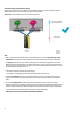
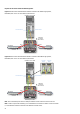
Note: The 8:1 Oversubscription with 2 FC cables per FlexFabric module is the most common use case.
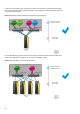
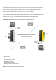
Note: In order to improve the redundancy, it is recommended to connect the FC cables in a crisscross manner
(i.e. each FlexFabric module is connected to two different controller nodes).