
HP Virtual Connect for c-Class BladeSystem Version 4.01 User Guide
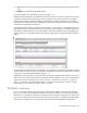
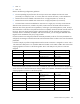
Table Of Contents
- HP Virtual Connect for c-Class BladeSystem Version 4.01 User Guide
- Abstract
- Notice
- Contents
- Introduction
- HP Virtual Connect Manager
- Virtual Connect domains
- Understanding Virtual Connect domains
- Managing domains
- Managing SNMP
- Viewing the system log
- Managing SSL configuration
- HP BladeSystem c-Class enclosures
- Virtual Connect users and roles
- Understanding VC administrative roles
- Managing users
- Local Users screen
- Configuring LDAP, RADIUS, and TACACS+
- Minimum requirements
- LDAP Server Settings (LDAP Server) screen
- LDAP Server Settings (LDAP Groups) screen
- LDAP Server Settings (LDAP Certificate) screen
- RADIUS Settings (RADIUS Server) screen
- RADIUS Settings (RADIUS Groups) screen
- TACACS+ Settings screen
- Role Management (Role Authentication Order) screen
- Role Management (Role Operations) screen
- Virtual Connect networks
- Understanding networks and shared uplink sets
- Managing networks
- Network Access Groups screen
- Define Network Access Group screen
- Ethernet Settings (Port Monitoring) screen
- Ethernet Settings (Advanced Settings) screen
- Quality of Service
- IGMP Settings (IGMP Configuration) screen
- IGMP Settings (Multicast Filter Set) screen
- Define Ethernet Network screen
- Ethernet Networks (External Connections) screen
- Ethernet Networks (Server Connections) screen
- Managing shared uplink sets
- Virtual Connect fabrics
- Virtual Connect server profiles
- Understanding server profiles
- Managing MAC, WWN, and server virtual ID settings
- Managing server profiles
- Define Server Profile screen
- Creating FCoE HBA connections for a BL890c i4
- Limited Ethernet connections when using HP Virtual Connect Flex-10/10D modules
- Creating iSCSI connections
- Flex-10 iSCSI connections
- Define Server Profile screen (multiple enclosures)
- Multiple network connections for a server port
- Defining server VLAN mappings
- Fibre Channel boot parameters
- Server Profiles screen
- Edit Server Profile screen
- Assigning a server profile with FCoE connections to an HP ProLiant BL680c G7 Server Blade
- Unassigning a server profile with FCoE connections to an HP ProLiant BL680c G7 Server Blade and deleting the SAN fabric
- General requirements for adding FC or FCoE connections
- Define Server Profile screen
- Virtual Connect and Insight Control Server Deployment
- Virtual Connect modules
- Firmware updates
- Stacking Links screen
- Throughput Statistics screen
- Enclosure Information screen
- Enclosure Status screen
- Interconnect Bays Status and Summary screen
- Causes for INCOMPATIBLE status
- Ethernet Bay Summary (General Information) screen
- Ethernet Bay Summary (Uplink Port Information) screen
- Ethernet Bay Summary (Server Port Information) screen
- Ethernet Bay Summary (MAC Address Table) screen
- Ethernet Bay Summary (IGMP Multicast Groups) screen
- Ethernet Bay Summary (Name Server) screen
- Ethernet Port Detailed Statistics screen
- FC Port Detailed Statistics screen
- FC Bay Summary screen
- Interconnect Bay Overall Status icon definitions
- Interconnect Bay OA Reported Status icon definitions
- Interconnect Bay VC Status icon definitions
- Interconnect Bay OA Communication Status icon definitions
- Server Bays Summary screen
- Server Bay Status screen
- Port status conditions
- Interconnect module removal and replacement
- Virtual Connect modules
- Upgrading to an HP Virtual Connect 8Gb 24-Port FC Module
- Upgrading to an HP Virtual Connect 8Gb 20-Port FC Module
- Upgrading or removing an HP Virtual Connect Flex-10, HP Virtual Connect FlexFabric, or HP Virtual Connect Flex-10/10D module
- Upgrading to an HP Virtual Connect FlexFabric module from a VC-FC module
- Onboard Administrator modules
- Maintenance and troubleshooting
- Appendix: Using Virtual Connect with nPartitions
- Support and other resources
- Acronyms and abbreviations
- Documentation feedback
- Index

Virtual Connect server profiles 162
and SAN boot settings and connects the appropriate networks and fabrics. Server blades that have been
assigned a profile and remain in the same device bay do not require further Virtual Connect Manager
configuration during a server or enclosure power cycle. They boot and gain access to the network and fabric
when the server and interconnect modules are ready.
If a server blade is installed in a device bay already assigned a server profile, Virtual Connect Manager
automatically updates the configuration of that server blade before it can power on and connect to the
network.
If a server blade is moved from a Virtual Connect-managed enclosure to a non-Virtual Connect enclosure, the
MAC addresses and WWNs for the blade are automatically returned to the original factory defaults. This
feature prevents duplicate MAC addresses and WWNs from appearing in the data center because of a
server blade redeployment.
Multi-blade servers
Certain HP Integrity server blades can be conjoined using a Blade Link to create a single server. These servers
are treated just like other server blades even though they are composed of several physical server blades.
IMPORTANT: The term server blade, when applied to a multi-blade server, means the entire
conjoined server, and not just a single server blade. For example, "a server profile is assigned to
a server blade" means that a single server profile is assigned to an entire multi-blade server.
In each multi-blade server, one blade is identified as the monarch blade. The other blades are referred to as
auxiliary blades. In multi-blade servers, the lowest numbered bay in the server is the monarch. Both the VCM
CLI and GUI identify the monarch in the information provided for a multi-blade server. All communication to
a multi-blade server, such as to the iLO user interface, is done through the monarch blade.
VCM displays multi-blade servers as a single entity, showing the range of bays that comprise the server. For
example, if a multi-blade server occupies bays 1, 2, 3, and 4, then VCM represents the server as “Bays 1-4
(HP Integrity BL890c i2).” This is true in the Server Bays summary screen, in the list of bays that a profile can
be assigned to in the Edit Server Profile screen, and so on.
A profile is assigned to an entire multi-blade server, not to the individual blades in the server. If a profile is
assigned to an auxiliary blade (for example, a profile is assigned to an empty bay and then a multi-blade
server is installed) that profile is ignored (in this case it’s the same as a profile assigned to a covered bay).
In such a case VCM identifies the bay that the profile is assigned to as “Covered – Auxiliary”.
VCM maps the profile connection entries to ports on the blades in a multi-blade server as follows:
• Ethernet profile connection entries are evenly distributed across all of the blades in a multi-blade server.
For example, if a multi-blade server is composed of 4 blades, then the 1st, 5th, 9th, and so forth Ethernet
connections are assigned to the first blade, the 2nd, 6th, 10th, and so forth Ethernet connections are
assigned to the second blade, and so forth. Connection entries to specific ports on a blade are mapped
the same way as for other full-height blades.
• FCoE profile connection entries are mapped to blades such that one FCoE profile entry is mapped to
one physical function on each CNA port on the first blade, then to CNA ports on the second blade, and
so on. However, this is not the case when using Integrity i4 blades that contain CNA LOMs. In that case,
LOMs 3 and 4 on each blade are skipped because each set of FCoE profile entries has one entry for
each I/O bay. The entries for I/O bays 1 and 2 get mapped to physical functions on LOMs 1 and 2.
To map FCoE entries to LOMs 3 and 4, you must first add enough FCoE entries to provide mappings to
CNA ports on every blade in a multi-blade server, and then additional entries can be added that will be
mapped to LOMs 3 and 4 on each blade.