
HP Virtual Connect for c-Class BladeSystem Version 4.01 User Guide
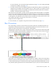
Table Of Contents
- HP Virtual Connect for c-Class BladeSystem Version 4.01 User Guide
- Abstract
- Notice
- Contents
- Introduction
- HP Virtual Connect Manager
- Virtual Connect domains
- Understanding Virtual Connect domains
- Managing domains
- Managing SNMP
- Viewing the system log
- Managing SSL configuration
- HP BladeSystem c-Class enclosures
- Virtual Connect users and roles
- Understanding VC administrative roles
- Managing users
- Local Users screen
- Configuring LDAP, RADIUS, and TACACS+
- Minimum requirements
- LDAP Server Settings (LDAP Server) screen
- LDAP Server Settings (LDAP Groups) screen
- LDAP Server Settings (LDAP Certificate) screen
- RADIUS Settings (RADIUS Server) screen
- RADIUS Settings (RADIUS Groups) screen
- TACACS+ Settings screen
- Role Management (Role Authentication Order) screen
- Role Management (Role Operations) screen
- Virtual Connect networks
- Understanding networks and shared uplink sets
- Managing networks
- Network Access Groups screen
- Define Network Access Group screen
- Ethernet Settings (Port Monitoring) screen
- Ethernet Settings (Advanced Settings) screen
- Quality of Service
- IGMP Settings (IGMP Configuration) screen
- IGMP Settings (Multicast Filter Set) screen
- Define Ethernet Network screen
- Ethernet Networks (External Connections) screen
- Ethernet Networks (Server Connections) screen
- Managing shared uplink sets
- Virtual Connect fabrics
- Virtual Connect server profiles
- Understanding server profiles
- Managing MAC, WWN, and server virtual ID settings
- Managing server profiles
- Define Server Profile screen
- Creating FCoE HBA connections for a BL890c i4
- Limited Ethernet connections when using HP Virtual Connect Flex-10/10D modules
- Creating iSCSI connections
- Flex-10 iSCSI connections
- Define Server Profile screen (multiple enclosures)
- Multiple network connections for a server port
- Defining server VLAN mappings
- Fibre Channel boot parameters
- Server Profiles screen
- Edit Server Profile screen
- Assigning a server profile with FCoE connections to an HP ProLiant BL680c G7 Server Blade
- Unassigning a server profile with FCoE connections to an HP ProLiant BL680c G7 Server Blade and deleting the SAN fabric
- General requirements for adding FC or FCoE connections
- Define Server Profile screen
- Virtual Connect and Insight Control Server Deployment
- Virtual Connect modules
- Firmware updates
- Stacking Links screen
- Throughput Statistics screen
- Enclosure Information screen
- Enclosure Status screen
- Interconnect Bays Status and Summary screen
- Causes for INCOMPATIBLE status
- Ethernet Bay Summary (General Information) screen
- Ethernet Bay Summary (Uplink Port Information) screen
- Ethernet Bay Summary (Server Port Information) screen
- Ethernet Bay Summary (MAC Address Table) screen
- Ethernet Bay Summary (IGMP Multicast Groups) screen
- Ethernet Bay Summary (Name Server) screen
- Ethernet Port Detailed Statistics screen
- FC Port Detailed Statistics screen
- FC Bay Summary screen
- Interconnect Bay Overall Status icon definitions
- Interconnect Bay OA Reported Status icon definitions
- Interconnect Bay VC Status icon definitions
- Interconnect Bay OA Communication Status icon definitions
- Server Bays Summary screen
- Server Bay Status screen
- Port status conditions
- Interconnect module removal and replacement
- Virtual Connect modules
- Upgrading to an HP Virtual Connect 8Gb 24-Port FC Module
- Upgrading to an HP Virtual Connect 8Gb 20-Port FC Module
- Upgrading or removing an HP Virtual Connect Flex-10, HP Virtual Connect FlexFabric, or HP Virtual Connect Flex-10/10D module
- Upgrading to an HP Virtual Connect FlexFabric module from a VC-FC module
- Onboard Administrator modules
- Maintenance and troubleshooting
- Appendix: Using Virtual Connect with nPartitions
- Support and other resources
- Acronyms and abbreviations
- Documentation feedback
- Index
Virtual Connect server profiles 166
FlexFabric module uplink ports X1-X4 can be configured as FC fabric ports or Ethernet network ports. If a port
is configured as an FC fabric port, the protocol used is FCoE, and the server profile connection to that fabric
is an FCoE connection.
Because of the many possible configurations of the FlexFabric module, pluggable modules can differ for each
uplink port on the FlexFabric module. If the uplink port is being used for an FC fabric, an SFP-FC connector
is required. SFP speeds of 2Gb, 4Gb, or 8Gb are supported for this configuration. A 1G SFP connector is not
supported on ports X1-X4 for either Ethernet or FC configurations. For Ethernet ports, the 10GbE SFP-LRM
pluggable module is not supported on ports X1-X4. The Ethernet SFP-LR and SFP-SR are supported on all
ports.
In a multi-enclosure environment, all enclosures must have the same VC-FC and FlexFabric module
configuration. For example, if the local enclosure has VC-FC modules in bays 3 and 4, each remote
enclosure must also have VC-FC modules in bays 3 and 4. This is called an FC bay group. Support for FC bay
groups with FlexFabric modules is similar to support for existing VC-FC modules. FlexFabric module bay
groups cannot contain any other type of VC-FC module, and any other VC-FC bay group cannot contain a
FlexFabric module. These module types are incompatible in the same bay group. For more information, see
the HP Virtual Connect for c-Class BladeSystem Setup and Installation Guide on the Installing tab of the HP
BladeSystem Technical Resources website (http://www.hp.com/go/bladesystem/documentation).
When an available port is used for Ethernet, it is no longer available for FC configuration, and vice-versa.
Likewise, a port that is removed from a network, shared uplink set, or fabric becomes available for
configuration of another network or fabric.
The FlexFabric VC module requirements also imply some additional constraints with current VC FC
requirements for bay groups. When a network is configured on a FlexFabric module using FC-capable ports,
those ports across the bay group are configured as Ethernet ports, becoming unavailable for FC. The similar
case applies when selecting the port type as FC.
There is a limitation on the NC551i LOM and the NC551m mezzanine card. FCoE and iSCSI connections
are not supported on the same adapter at the same time. By default, if a FlexFabric module is found in the
enclosure, FCoE connections are created for each server profile. If you do not wish to configure FCoE
connections, delete the default connections to allow the ports to be used for other connections, such as iSCSI
or additional Ethernet connections. To delete the connections, right-click the connection, and then select
Delete Connection.
There are additional limitations with the supported LOMs and mezzanine cards that support FlexFabric
configurations. Both FCoE boot and PXE can be configured on the same port with the NC551i LOM and the
NC551m mezzanine card on different physical functions. Alternatively, iSCSI and PXE can be configured on
the same port. Only one physical function can be configured for FCoE on a port.
When configuring FCoE connections, the port speed can be set to 1Gb, 2Gb, 4Gb, 8Gb, custom, preferred,
or disabled. The port speed is limited to a total of 10Gb, which must be shared between all defined
connections for that port. The custom speed allows you to better control the bandwidth between FC and
Ethernet connections. Valid custom speeds are between 100Mb and 10Gb, in 100Mb increments. After all
connections are defined for a port, the actual allocated bandwidth is calculated by VCM. For bandwidth
information, see “Bandwidth Assignment (on page 171)."
PXE settings
Virtual Connect Manager supports three PXE options:
• Enable—VC Manager sends a configuration update to the mezzanine NIC or embedded NIC
associated with the port to enable PXE operations.