
HP Virtual Connect for c-Class BladeSystem Version 4.01 User Guide

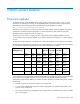
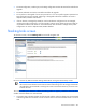
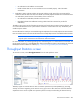
Table Of Contents
- HP Virtual Connect for c-Class BladeSystem Version 4.01 User Guide
- Abstract
- Notice
- Contents
- Introduction
- HP Virtual Connect Manager
- Virtual Connect domains
- Understanding Virtual Connect domains
- Managing domains
- Managing SNMP
- Viewing the system log
- Managing SSL configuration
- HP BladeSystem c-Class enclosures
- Virtual Connect users and roles
- Understanding VC administrative roles
- Managing users
- Local Users screen
- Configuring LDAP, RADIUS, and TACACS+
- Minimum requirements
- LDAP Server Settings (LDAP Server) screen
- LDAP Server Settings (LDAP Groups) screen
- LDAP Server Settings (LDAP Certificate) screen
- RADIUS Settings (RADIUS Server) screen
- RADIUS Settings (RADIUS Groups) screen
- TACACS+ Settings screen
- Role Management (Role Authentication Order) screen
- Role Management (Role Operations) screen
- Virtual Connect networks
- Understanding networks and shared uplink sets
- Managing networks
- Network Access Groups screen
- Define Network Access Group screen
- Ethernet Settings (Port Monitoring) screen
- Ethernet Settings (Advanced Settings) screen
- Quality of Service
- IGMP Settings (IGMP Configuration) screen
- IGMP Settings (Multicast Filter Set) screen
- Define Ethernet Network screen
- Ethernet Networks (External Connections) screen
- Ethernet Networks (Server Connections) screen
- Managing shared uplink sets
- Virtual Connect fabrics
- Virtual Connect server profiles
- Understanding server profiles
- Managing MAC, WWN, and server virtual ID settings
- Managing server profiles
- Define Server Profile screen
- Creating FCoE HBA connections for a BL890c i4
- Limited Ethernet connections when using HP Virtual Connect Flex-10/10D modules
- Creating iSCSI connections
- Flex-10 iSCSI connections
- Define Server Profile screen (multiple enclosures)
- Multiple network connections for a server port
- Defining server VLAN mappings
- Fibre Channel boot parameters
- Server Profiles screen
- Edit Server Profile screen
- Assigning a server profile with FCoE connections to an HP ProLiant BL680c G7 Server Blade
- Unassigning a server profile with FCoE connections to an HP ProLiant BL680c G7 Server Blade and deleting the SAN fabric
- General requirements for adding FC or FCoE connections
- Define Server Profile screen
- Virtual Connect and Insight Control Server Deployment
- Virtual Connect modules
- Firmware updates
- Stacking Links screen
- Throughput Statistics screen
- Enclosure Information screen
- Enclosure Status screen
- Interconnect Bays Status and Summary screen
- Causes for INCOMPATIBLE status
- Ethernet Bay Summary (General Information) screen
- Ethernet Bay Summary (Uplink Port Information) screen
- Ethernet Bay Summary (Server Port Information) screen
- Ethernet Bay Summary (MAC Address Table) screen
- Ethernet Bay Summary (IGMP Multicast Groups) screen
- Ethernet Bay Summary (Name Server) screen
- Ethernet Port Detailed Statistics screen
- FC Port Detailed Statistics screen
- FC Bay Summary screen
- Interconnect Bay Overall Status icon definitions
- Interconnect Bay OA Reported Status icon definitions
- Interconnect Bay VC Status icon definitions
- Interconnect Bay OA Communication Status icon definitions
- Server Bays Summary screen
- Server Bay Status screen
- Port status conditions
- Interconnect module removal and replacement
- Virtual Connect modules
- Upgrading to an HP Virtual Connect 8Gb 24-Port FC Module
- Upgrading to an HP Virtual Connect 8Gb 20-Port FC Module
- Upgrading or removing an HP Virtual Connect Flex-10, HP Virtual Connect FlexFabric, or HP Virtual Connect Flex-10/10D module
- Upgrading to an HP Virtual Connect FlexFabric module from a VC-FC module
- Onboard Administrator modules
- Maintenance and troubleshooting
- Appendix: Using Virtual Connect with nPartitions
- Support and other resources
- Acronyms and abbreviations
- Documentation feedback
- Index
Virtual Connect modules 226
o
OK indicates that all modules are connected.
o Failed indicates that one or more modules are not connected properly. Check the cable
connections.
• Redundancy Status indicates whether all VC-Enet modules would remain fully interconnected if a
module or external cable was removed or failed. Horizontally-adjacent modules are considered to have
OK redundancy status because of the reliability of their internal link.
o OK indicates that redundant/reliable connections exist.
o Degraded indicates that additional stacking cables should be connected to provide full
redundancy.
The table on this screen lists all of the Ethernet stacking links found within the Virtual Connect domain. Each
row of the table identifies the link speed and the connections on both sides of the link, identified by the
module and port number.
Port X0 indicates the 10Gb port connected through the midplane of horizontally-adjacent VC-Enet modules.
Ports X7 and X8 connect to the internal link between horizontally-adjacent Flex-10 enabled VC-Enet modules.
NOTE: Virtual Connect does not support stacking for FC modules, so each VC-FC module
requires uplink connections to the external FC SAN environment.
For more information on connecting stacking links, and stacking links in a multi-enclosure environment, see
the HP Virtual Connect for c-Class BladeSystem Setup and Installation Guide on the Installing tab of the HP
BladeSystem Technical Resources website (http://www.hp.com/go/bladesystem/documentation).
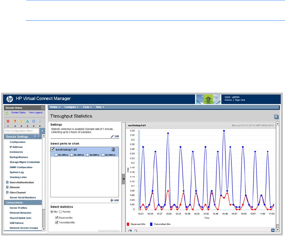
Throughput Statistics screen
To access this screen, select Throughput Statistics from the Tools pull-down menu.
Telemetry support for network devices caters to seamless operations and interoperability by providing
visibility into what is happening on the network at any given time. It offers extensive and useful detection
capabilities which can be coupled with upstream systems for analysis and trending of observed activity.