
HP Virtual Connect for c-Class BladeSystem Version 4.01 User Guide
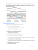
Table Of Contents
- HP Virtual Connect for c-Class BladeSystem Version 4.01 User Guide
- Abstract
- Notice
- Contents
- Introduction
- HP Virtual Connect Manager
- Virtual Connect domains
- Understanding Virtual Connect domains
- Managing domains
- Managing SNMP
- Viewing the system log
- Managing SSL configuration
- HP BladeSystem c-Class enclosures
- Virtual Connect users and roles
- Understanding VC administrative roles
- Managing users
- Local Users screen
- Configuring LDAP, RADIUS, and TACACS+
- Minimum requirements
- LDAP Server Settings (LDAP Server) screen
- LDAP Server Settings (LDAP Groups) screen
- LDAP Server Settings (LDAP Certificate) screen
- RADIUS Settings (RADIUS Server) screen
- RADIUS Settings (RADIUS Groups) screen
- TACACS+ Settings screen
- Role Management (Role Authentication Order) screen
- Role Management (Role Operations) screen
- Virtual Connect networks
- Understanding networks and shared uplink sets
- Managing networks
- Network Access Groups screen
- Define Network Access Group screen
- Ethernet Settings (Port Monitoring) screen
- Ethernet Settings (Advanced Settings) screen
- Quality of Service
- IGMP Settings (IGMP Configuration) screen
- IGMP Settings (Multicast Filter Set) screen
- Define Ethernet Network screen
- Ethernet Networks (External Connections) screen
- Ethernet Networks (Server Connections) screen
- Managing shared uplink sets
- Virtual Connect fabrics
- Virtual Connect server profiles
- Understanding server profiles
- Managing MAC, WWN, and server virtual ID settings
- Managing server profiles
- Define Server Profile screen
- Creating FCoE HBA connections for a BL890c i4
- Limited Ethernet connections when using HP Virtual Connect Flex-10/10D modules
- Creating iSCSI connections
- Flex-10 iSCSI connections
- Define Server Profile screen (multiple enclosures)
- Multiple network connections for a server port
- Defining server VLAN mappings
- Fibre Channel boot parameters
- Server Profiles screen
- Edit Server Profile screen
- Assigning a server profile with FCoE connections to an HP ProLiant BL680c G7 Server Blade
- Unassigning a server profile with FCoE connections to an HP ProLiant BL680c G7 Server Blade and deleting the SAN fabric
- General requirements for adding FC or FCoE connections
- Define Server Profile screen
- Virtual Connect and Insight Control Server Deployment
- Virtual Connect modules
- Firmware updates
- Stacking Links screen
- Throughput Statistics screen
- Enclosure Information screen
- Enclosure Status screen
- Interconnect Bays Status and Summary screen
- Causes for INCOMPATIBLE status
- Ethernet Bay Summary (General Information) screen
- Ethernet Bay Summary (Uplink Port Information) screen
- Ethernet Bay Summary (Server Port Information) screen
- Ethernet Bay Summary (MAC Address Table) screen
- Ethernet Bay Summary (IGMP Multicast Groups) screen
- Ethernet Bay Summary (Name Server) screen
- Ethernet Port Detailed Statistics screen
- FC Port Detailed Statistics screen
- FC Bay Summary screen
- Interconnect Bay Overall Status icon definitions
- Interconnect Bay OA Reported Status icon definitions
- Interconnect Bay VC Status icon definitions
- Interconnect Bay OA Communication Status icon definitions
- Server Bays Summary screen
- Server Bay Status screen
- Port status conditions
- Interconnect module removal and replacement
- Virtual Connect modules
- Upgrading to an HP Virtual Connect 8Gb 24-Port FC Module
- Upgrading to an HP Virtual Connect 8Gb 20-Port FC Module
- Upgrading or removing an HP Virtual Connect Flex-10, HP Virtual Connect FlexFabric, or HP Virtual Connect Flex-10/10D module
- Upgrading to an HP Virtual Connect FlexFabric module from a VC-FC module
- Onboard Administrator modules
- Maintenance and troubleshooting
- Appendix: Using Virtual Connect with nPartitions
- Support and other resources
- Acronyms and abbreviations
- Documentation feedback
- Index

Virtual Connect networks 84
Virtual Connect networks
Understanding networks and shared uplink sets
The VC-Enet modules use standard Ethernet bridge circuitry with special firmware so that they function as a
configurable Ethernet port aggregator. For a specific external data center connection, only the selected
server Ethernet NIC ports are visible on what appears to be an isolated, private, loop-free network. The
VC-Enet module uplinks do not participate in the data center Spanning Tree Protocol or other switch
management protocols that could disrupt the data center network.
The VC-Enet module uplinks support link aggregation, link layer discovery protocol (LLDP), and VLAN
tagging. VLAN tagging enables uplinks to be shared to carry multiple networks.
Each network defined within VCM can have one or more uplinks. Virtual Connect independently ensures that
no loops are created within the VC domain and that the resulting tree structure is optimized for the uplinks to
the data center.
When multiple uplinks are used on a network, VCM first verifies if any of the ports can be collected together
into an aggregation group, which requires connections to go from a single VC-Enet module to a single data
center switch. Then, VCM picks a single link (or aggregation group) as the connection to the external
network. The remaining connections are blocked and held as standby ports.
TIP: To improve network performance and prevent unnecessary Spanning Tree Topology
Change Notifications (TCN) on the network, configure Ethernet switches connected to Virtual
Connect with the same Spanning Tree settings you would use when connecting to a server blade
NIC. For Cisco switches, use the portfast command to enable ports connected to a VC-Enet
module. This action ensures that link state changes on Virtual Connect do not cause a TCN.
Shared uplink sets and VLAN tagging
A shared uplink set identifies VC-Enet module uplinks that carry multiple networks over the same cable or set
of cables. In this case, each Ethernet packet carries a VLAN tag (IEEE 802.1Q) to identify the specific
network to which it belongs. On shared uplinks, the VLAN tags are added when packets leave the
VC-enabled enclosure and are removed when packets enter the enclosure. The external Ethernet switch and
VCM must be configured to use the same VLAN tag identifier (a number between 1 and 4094) for each
network.
Virtual Connect places no special restrictions on which VLAN identifiers can be used, so the VLAN IDs
already used for the networks in the data center can be used on these shared uplinks. To configure a shared
uplink set for VLAN tagging, obtain a list of the network names and their VLAN IDs.
A shared uplink set enables multiple ports to be included to support port aggregation and link failover with
a consistent set of VLAN tags.
Because VLAN tags are added or removed when Ethernet packets leave or enter the VC-Enet shared uplink,
the VLAN tags have no relevance after the Ethernet packet enters the enclosure.