Technical white paper FC Cookbook for HP Virtual Connect Version 4.
redundant SAN fabric with different priority tiers Overview Benefits Considerations Requirements Installation and configuration Verification of the SAN Fabrics configuration Blade Server configuration Verification Summary Scenario 4: Multiple VC Fabric-Attach SAN fabrics with Dynamic Login Balancing connected to several redundant SAN fabric with different priority tiers Overview Benefits Considerations Requirements Installation and configuration Verification of the SAN Fabrics configuration Blade Server con
Benefits Considerations Physical view of a Direct-Attach configuration Requirements Installation and configuration Configuration of the 3PAR controller ports Verification of the 3PAR connection Blade Server configuration OS Configuration Summary 78 78 79 79 79 83 85 85 87 87 Scenario 7: Mixed Fabric-Attach and Flat SAN connectivity with HP Virtual Connect FlexFabric 10Gb/24-Port modules and HP 3PAR Storage Systems Overview Considerations Physical view of a mix Flat SAN and Fabric-Attach configuration Requ
Summary Scenario 10: Fabric-Attach SAN fabrics connectivity with HP Virtual Connect FlexFabric-20/40 F8 module Overview Benefits Considerations Virtual Connect FlexFabric-20/40 F8 Uplink Port Mappings Requirements Installation and configuration Verification of the SAN Fabrics configuration Blade Server configuration Summary Appendix A: Blade Server configuration with Virtual Connect Fibre Channel Modules Defining a Server Profile with FC Connections, using the GUI Defining a Server Profile with FC Connectio
Enabling NPIV using the CLI Appendix E: Connecting VC FlexFabric to Cisco Nexus 50xx and 55xx series Support information Fibre Channel functions on Nexus Configuration of the VC SAN Fabric Configuration of the Nexus switches Appendix F: Connectivity verification and testing Uplink Port connectivity verification Uplink Port connection issues Server Port connectivity verification Server Port connection issues Connectivity verification from the upstream SAN switch Testing the loss of uplink ports 143 145 145
Abstract This guide provides concepts and implementation steps for integrating HP Virtual Connect Fibre Channel modules and HP Virtual Connect FlexFabric Modules into an existing SAN Fabric. The scenarios in this guide cover a range of typical building blocks to use when designing a solution. For more information on BladeSystem and Virtual Connect, go to http://www.hp.
Considerations and concepts The following concepts apply when using the Virtual Connect Fibre Channel Module or the Virtual Connect FlexFabric module: To manage an HP VC-FC Module, you must also install an HP Virtual Connect Ethernet Module. The VC Ethernet module contains the processor on which the Virtual Connect Manager firmware runs. Virtual Connect now supports Direct Storage attachment to reduce storage networking costs and to remove the complexity of FC switch management.
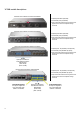
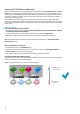
VC SAN module descriptions HP Virtual Connect 8Gb 20-Port Fibre Channel Module 4 Uplink ports 8Gb FC [2/4/8 Gb] 16 Downlink ports [1/2/4/8 Gb] Up to 128 virtual machines running on the same physical server to access separate storage resources HP Virtual Connect 8Gb 24-Port Fibre Channel Module 8 Uplink ports 8Gb FC [2/4/8 Gb] 16 Downlink ports [1/2/4/8 Gb] Up to 255 virtual machines running on the same physical server to access separate storage resources HP Virtual Connect FlexFabric 10Gb/2
Virtual Connect Fibre Channel support Virtual Connect Connectivity Stream documents that describe the different supported configurations are available from the SPOCK webpage: www.hp.com/storage/spock (Requires HP Passport; if you do not have an HP Passport account, follow the instructions on the webpage). For any specific, supported Fabric OS, SAN-OS, or NX-OS versions for SAN that involve 3rd-party equipment, consult the equipment vendor.
Supported VC SAN Fabric configuration Beginning with Virtual Connect 3.70, there are two supported VC SAN fabric types, Fabric-Attach fabrics and DirectAttach fabrics. A Fabric-Attach fabric uses the traditional method of connecting VC-FC and VC FlexFabric modules, which requires an upstream NPIV-enabled SAN switch.
Figure 2: A same SAN Fabric can consist of several SAN switches. In the following configuration, each SAN Fabric has two SAN switches, and the previous “Participating uplinks must connect to the same SAN fabric” prerequisite is met.
Figure 5: Direct Attached Storage Systems are not supported VC SAN 1 VC FlexFabric Module 3PAR, MSA, EVA or XP Figure 5 and Figure 6 show two typical, supported configurations for Virtual Connect Fibre Channel 8Gb 20-port and Virtual Connect FlexFabric modules. Figure 6: Typical Fabric-Attach SAN configuration with VC-FC 8Gb 20-port modules.
Figure 7: Typical Fabric-Attach SAN configuration with VC FlexFabric modules.
Multiple Fabric-Attach fabric Support Support for multiple SAN Fabric-Attach fabrics per VC-FC and FlexFabric modules allows the Storage administrator to assign any of the available VC SAN uplinks to a different SAN fabric and dynamically assign server HBAs to the desired SAN fabric.
NPIV requirements for VC Fabric-Attach fabrics Uplink ports within a VC Fabric-Attach fabric can only be connected to Fibre Channel switch that supports N_port_ID virtualization (NPIV). The VC-FC and VC FlexFabric modules are FC standards-based and are compatible with all other NPIV standard– compliant switch products.
Increased bandwidth Depending on the VC Fibre Channel module and the number of uplinks used, the server-to-uplink ratio (oversubscription ratio) is adjustable to 2:1, 4:1, 8:1, or 16:1. As few as two or as many as 16 servers share one physical link on a fully populated enclosure with 16 servers. Using multiple uplinks reduces the risk of congestion.
Uplink port path failover The module uses dynamic login distribution to provide an uplink port path failover that enables server connections to fail over within the Virtual Connect fabric. If a fabric uplink port in the group becomes unavailable, hosts logged in through that uplink are reconnected automatically to the fabric through the remaining uplinks in the group, resulting in auto-failover.
Login Redistribution If a failed port becomes available again, the login redistribution (or login failback) is not automatic unless you have configured Automatic Login Redistribution, which is available with the VC FlexFabric modules.
Link stability This interval defines the number of seconds that the VC fabric uplinks have to stabilize before the VC FC module attempts to load-balance the logins. The administrator can configure the link stability interval parameter on a VC domain basis. You can enable Automatic Login Redistribution for VC FlexFabric. For all legacy VC-FC modules, the Login Redistribution is manual only.
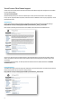
Manual Logins redistribution To manually redistribute logins on a VC SAN fabric: 1. Select the VC SAN Fabric. 2. Select the Server connections tab, and then click Redistribute Logins. Redistribute Logins is only valid for a VC SAN fabric with Manual Login Distribution.
Flat SAN Support With HP Virtual Connect for 3PAR with Flat SAN technology, you can connect HP 3PAR Storage Systems directly to HP Virtual Connect FlexFabric Modules with no need for an intermediate SAN fabric. This significantly reduces complexity and cost while reducing latency between servers and storage by eliminating the need for multitier storage area networks (SANs). This direct attachment lets you worry less about storage solution complexity.
Maximum number of c-Class enclosures connected to a HP 3PAR storage system Connecting several BladeSystem c-Class enclosures to the same 3PAR Storage system is fully supported. The number of host ports available on the HP 3PAR controller nodes defines the maximum number of enclosures supported. With 4 controller nodes, a 3PAR StoreServ 10400 can support up to 96 Fibre Channel Host Ports.
Virtual Connect Direct-Attach SAN Fabric support When using the Virtual Connect Direct-Attach mode, participating uplinks can be directly connected to the same 3PAR Storage System in order to correctly form a Virtual Connect SAN fabric.
In order to give more granular control over which server blades use each uplink port, several Direct-Attach VC SAN fabrics can be connected to the same 3PAR storage System. This configuration can enable the distribution of servers according to their I/O workloads.
To support more than four direct-attached 3PAR arrays, it is necessary to add more pairs of VC FlexFabric modules in a c7000 chassis.
Unsupported Virtual Connect Direct-Attach SAN Fabric configurations When using the Direct-Attach mode, participating uplinks must be directly connected to a 3PAR Storage System. Any other storage systems are not supported.
Physical view of a Direct-Attach Flat SAN configuration Figure 27: Virtual Connect Flat SAN with VC FlexFabric modules for HP 3PAR Storage Systems, Redundant paths - Server-to- Direct-Attach uplink ratio 16:1 HP 3PAR StoreServ 10400 Controller Node 0 Controller Node 1 SAN uplink connections (Direct-Attach) FAN 1 FAN 5 SHARED: UPLINK or X-LINK X1 X2 X3 X4 X5 X6 X7 SHARED: UPLINK or X-LINK X1 X8 UID X2 X3 X4 X5 X6 X7 X8 UID 2 1 HP VC FlexFabric 10Gb/24-Port Module SUS-1 LAN Switch
Remote replication design with Virtual Connect Flat SAN technology HP 3PAR Data replication services provide real-time replication and disaster recovery technology that allows the protection and sharing of data. You can implement the data replication services between HP 3PAR Storage arrays to distribute data between local and remote arrays or data centers, even if they are geographically dispersed.
Details about the 3PAR controller connectivity HP 3PAR Controller Nodes are always installed in pairs, and a system can support from 2 to 8 controllers. 9 PCI-e slots are available per controller node and are used for both host and drive chassis connections using HP 3PAR Host/Disk Adapters. As a best practice, HP recommends using PCI slots 2, 5, 8, 1, 4, 7 for the Direct-Attach FlexFabric connections. These PCI slots are also recommended for the host connections.
Mixed Fabric-Attach and Flat SAN mode support You can mix Virtual Connect Fabric-Attach and Direct-Attach Flat SAN fabrics on a same Virtual Connect domain. This mix is useful if an administrator needs to attach additional storage systems that are not supported today with the Direct-Attach mode.
Figure 33: Typical mix Fabric-Attach and Direct-Attach FC configuration with VC FlexFabric modules.
Backup design for a Direct Attached 3PAR solution Disk or Tape backup systems cannot be directly attached to FlexFabric modules. Instead, you must use a SAN Fabric or a LAN-based solution, which are common for use with backup solutions.
Multi-enclosure stacking configuration Virtual Connect version 2.10 and higher supports the connection of up to four c7000 enclosures, which can reduce the number of network connections per rack and also enables a single VC manager to control multiple enclosures. For more information, see HP Virtual Connect Multi-Enclosure Stacking Reference Guide in the “Related Documentation“ section at the end of this document.
Figure 36: Unsupported Multi-Enclosure Stacking configuration Storage Array Mgmt UID PS 1 Cntrl 1 PS 2 Cntrl 2 UID 1 2 DP1-A UID DP1-B 1 2 DP1-A DP1-B Mfg Mfg Storage Controller Storage Controller Fabric attached Storage Systems Fabric-1 Fabric-2 0 4 1 5 2 6 3 7 8 12 9 13 10 14 11 15 16 20 17 21 18 22 19 23 24 28 25 29 26 30 27 0 31 12Vdc 4 1 5 2 6 3 7 8 12 9 13 10 14 11 15 16 20 17 21 18 22 19 23 24 28 25 29 26 30 27 31 1
Multi-enclosure stacking with Flat SAN Technology When using HP Virtual Connect for 3PAR with Flat SAN technology in a VC Multi Enclosure environment: All VC FlexFabric modules must be connected to the 3PAR Storage System(s). Server profile migration of a SAN-booted server between enclosures is not supported.
Scenario 1: Simplest scenario with multipathing Overview This scenario covers the setup and configuration of two VC Fabric-Attach SAN Fabrics, each using a single uplink connected to a redundant Fabric.
Figure 39: Physical view Storage Array Mgmt UID PS 1 Cntrl 1 PS 2 Cntrl 2 UID 1 2 DP1-A UID DP1-B 1 2 DP1-A DP1-B Mfg Mfg Fabric-1 Fabric-2 0 4 1 5 2 6 3 7 8 12 9 13 10 14 11 15 16 20 17 21 18 22 19 23 24 28 25 29 26 30 27 0 31 12Vdc 4 1 5 2 6 3 7 8 12 9 13 10 14 11 15 16 20 12Vdc 12Vdc 17 21 18 22 19 23 24 28 25 29 26 30 27 31 12Vdc HP StorageWorks 4/32B SAN Switch HP StorageWorks 4/32B SAN Switch 1 2 3 1 4 2 3
Installation and configuration Switch configuration Appendices B, C and D provide the steps required to configure NPIV on the upstream SAN switch in a Brocade, Cisco Nexus or Cisco MDS Fibre Channel infrastructure. VC CLI commands In addition to the GUI, many of the configuration settings within VC can be established using a CLI command set. In order to connect to VC using a CLI, open an SSH connection to the IP address of the active VCM. Once logged in, VC provides a CLI with help menus.
1. From the HP Virtual Connect Manager GUI, select Define SAN Fabric from the HP Virtual Connect Home page. 2. From the Define SAN Fabric dialog, provide the VC Fabric Name, in this case Fabric-1, and add the Fabric uplink Port 1 from the first VC-FC module. 3. Click Apply. 4. On the SAN Fabrics screen, click Add to create the second fabric: 5. Create a new VC Fabric named Fabric-2. 6. Under Enclosure Uplink Ports, add Port 1 from the second VC-FC module, and then click Apply.
Two VC SAN fabrics have been created, each with one uplink port allocated from one VC module. Defining a new VC SAN Fabric using CLI Configure the VC-FC modules from the CLI. 1. Log in to the Virtual Connect Manager CLI: 2. Enter the following commands to create the fabrics and assign the uplink ports: add fabric Fabric-1 Bay=5 Ports=1 add fabric Fabric-2 Bay=6 Ports=1 3. 40 When complete, run the show fabric command.
Blade Server configuration Server profile configuration steps can be found in Appendix A. Verification See Appendix F and Appendix G for verifications and troubleshooting steps. Summary In this scenario you have created two FC SAN Fabrics, utilizing a single uplink each; this is the simplest scenario that can be used to maximize the use of the VC-FC uplink ports and reduce the number of datacenter SAN ports. A multipathing driver is required for transparent failover between the two server HBA ports.
Scenario 2: VC Fabric-Attach SAN fabrics with Dynamic Login Balancing connected to the same redundant SAN fabric Overview This scenario covers the setup and configuration of two VC Fabric-Attach SAN Fabrics with Dynamic Login Balancing Distribution, each utilizing two to eight uplink ports connected to a redundant Fabric.
Figure 41: 4:1 oversubscription with VC-FC 8Gb 20-Port modules using 8 uplink ports 4:1 server-to-uplink ratio on a fully populated enclosure with 16 servers Server 1 Server 2 Server 16 Server 3 … HBA1 HBA2 HBA1 HBA2 HBA1 HBA2 HBA1 HBA2 … VC Domain Fabric-2 Fabric-1 VC-FC 8Gb 20-port Module Fabric 1 Fabric 2 Figure 42: 2:1 oversubscription with VC-FC 8Gb 24-Port modules using 16 uplink ports 2:1 server-to-uplink ratio on a fully populated enclosure with 16 servers Server 1 Server 2 Ser
Figure 43: Physical view Storage Array Mgmt UID PS 1 Cntrl 1 PS 2 Cntrl 2 UID 1 2 DP1-A UID DP1-B 1 2 DP1-A DP1-B Mfg Mfg Fabric-1 Fabric-2 0 4 1 5 2 6 3 7 8 12 9 13 10 14 11 15 16 20 17 21 18 22 19 23 24 28 25 29 26 30 27 0 31 12Vdc 4 1 5 2 6 3 7 8 12 9 13 10 14 11 15 16 12Vdc 12Vdc 20 17 21 18 22 19 23 24 28 25 29 26 30 27 31 12Vdc HP StorageWorks 4/32B SAN Switch HP StorageWorks 4/32B SAN Switch 1 2 3 1 4 2 3
Installation and configuration Switch configuration Appendices B, C and D provide the steps required to configure NPIV on the upstream SAN switch in a Brocade, Cisco MDS or Cisco Nexus Fibre Channel infrastructure. VC CLI commands In addition to the GUI, you can complete many of the configuration settings within VC using a CLI command set. In order to connect to VC using a CLI, open an SSH connection to the IP address of the active VCM. Once logged in, VC provides a CLI with help menus.
2. In the Define SAN Fabric screen, provide the VC Fabric Name, in this case Fabric-1. 3. Add the uplink ports that will be connected to this fabric, and then click Apply. The following example uses Port 1, Port 2, Port 3 and Port 4 from the first VC-FC module (Bay 5). 4.
5. Create a new VC Fabric named Fabric-2 and add the uplink ports that will be connected to this fabric, and then click Apply. The following example uses Port 1, Port 2, Port 3 and Port 4 from the second VC-FC module (Bay 6). 6. You have created two VC Fabric-Attach SAN fabrics each with four uplink ports allocated from a VC module in Bay 5 and a VC module in Bay6.
Defining a new VC SAN Fabric using the CLI Configure the VC-FC modules from the CLI: 1. Log in to the Virtual Connect Manager CLI: 2. Enter the following commands to create the fabrics and assign the uplink ports: add fabric Fabric-1 Bay=5 Ports=1,2,3,4 add fabric Fabric-2 Bay=6 Ports=1,2,3,4 3. When complete, run the show fabric command.
Blade Server configuration and verification See Appendix A for server profile configuration steps. See Appendix F and Appendix G for verifications and troubleshooting steps. Summary This scenario shows two FC SAN Fabric-Attach fabrics with multiple uplink ports using Dynamic Login Distribution which allows for login balancing and host connectivity auto failover. This configuration enables increased performance and improved availability.
Scenario 3: Multiple VC Fabric-Attach SAN fabrics with Dynamic Login Balancing connected to the same redundant SAN fabric with different priority tiers Overview This scenario covers the setup and configuration of four VC Fabric-Attach SAN fabrics with Dynamic Login Balancing Distribution that are all connected to the same redundant SAN fabric.
Figure 45: Physical view Storage Array Mgmt UID PS 1 Cntrl 1 PS 2 Cntrl 2 UID 1 2 DP1-A UID DP1-B 1 2 DP1-A DP1-B Mfg Mfg Fabric-1 Fabric-2 0 4 1 5 2 6 3 7 8 12 9 13 10 14 11 15 16 20 17 21 18 22 19 23 24 28 25 29 26 30 27 0 31 12Vdc 4 1 5 2 6 3 7 8 12 9 13 10 14 11 15 16 20 12Vdc 12Vdc 17 21 18 22 19 23 24 28 25 29 26 30 27 31 12Vdc HP StorageWorks 4/32B SAN Switch HP StorageWorks 4/32B SAN Switch 1 2 3 1 4 2 3
Considerations A multipathing I/O driver must be running on the server Operating System to prevent server I/O disruption when a failure occurs somewhere between VC and the external fabric. This automatic failover allows smooth transition without much disruption to the traffic. However, the hosts must perform re-login before resuming their I/O operations.
1. From the HP Virtual Connect Manager GUI, select Define SAN Fabric from the HP Virtual Connect Home page. 2. From the Define SAN Fabric dialog, provide the VC Fabric Name, in this case Fabric-1-Tier1 3. Add the uplink ports that will be connected to this fabric, and then click Apply. The following example uses Port 1, Port 2 and Port 3 from the first VC-FC module (Bay 5).
4. On the SAN Fabrics screen, click Add to create the second fabric: 5. Create a new VC Fabric named Fabric-1-Tier2. 6. Under Enclosure Uplink Ports, add Bay 5, Port 4, and then click Apply. You have created two VC Fabric-Attach fabrics, each with uplink ports allocated from one VC module in Bay 5. One of the fabrics is configured with three 4Gb uplinks, and one is configured with one 4Gb uplink.
7.
You have created four VC Fabric-Attach fabrics, two for the server group Tier1 with three uplink ports and two for the guaranteed throughput server Tier2 with one uplink port. Defining a new VC SAN Fabric using the CLI Configure the VC-FC modules from the CLI: 1. Log in to the Virtual Connect Manager CLI: 2.
3. When complete, run the show fabric command. Verification of the SAN Fabrics configuration Make sure all the SAN fabrics belonging to the same Bay are connected to the same core FC SAN fabric switch. 1. Go to the SAN Fabrics screen. 2. The Connected To column displays the upstream SAN fabric switch to which the VC module uplink ports are connected. Verify that the entries from the same Bay number are all the same, indicating a single SAN fabric.
Blade Server configuration For server profile configuration steps, see Appendix A. After you have configured the VC SAN fabrics, you can select a Server Profile and choose the VC fabric to which you would like your HBA ports to connect. 1. Select the server profile, in this case esx4-1 2. Under FC HBA Connections, select the FC SAN fabric name to which you would like Port 1 Bay 5 to connect. Verification See Appendix F and Appendix G for verifications and troubleshooting steps.
Scenario 4: Multiple VC Fabric-Attach SAN fabrics with Dynamic Login Balancing connected to several redundant SAN fabric with different priority tiers Overview This scenario covers the setup and configuration of four VC Fabric-Attach SAN fabrics with Dynamic Login Balancing Distribution that are all connected to the different redundant SAN fabric.
Figure 47: Physical view Storage Array 1 Mgmt UID PS 1 Cntrl 1 PS 2 Cntrl 2 UID 1 2 DP1-A UID DP1-B 1 2 DP1-A Storage Array 2 DP1-B Mfg Mfg HP EVA HSV300 RS232 Invalid Address Host 0 Host 1 1 ID Fault Hub Mode 2Gb b 1Gb Host 2 Host 3 2G Host 3 2G b 1Gb Host 2 4Gb Host 0 Host 1 Fault 4Gb RS232 Fabric 1A 0 4 1 5 2 6 Fabric 1B 3 7 8 12 9 13 10 14 11 15 16 20 17 21 18 22 19 23 24 28 25 29 26 30 27 31 0 12Vdc 12Vdc 4 1 5 2 6 3 7 8
Requirements This configuration requires: At least two Fabric-Attach SAN fabrics with one or more switches that support NPIV At least one VC-FC module A minimum of two VC fabric uplinks connected to each of the SAN fabrics. For more information about configuring FC switches for NPIV, see "Appendix C: Brocade SAN switch NPIV configuration" or "Appendix D: Cisco MDS SAN switch NPIV configuration" or "Appendix E: Cisco NEXUS SAN switch NPIV configuration" depending on your switch model.
2. In the Define SAN Fabric screen, provide the VC Fabric Name, in this case Fabric-A-1 3. Add the uplink ports that will be connected to this fabric, and then click Apply. The following example uses Port 1, Port 2 and Port 3 from the first VC-FC module (Bay 5). 4. On the SAN Fabrics screen, click Add to create the second fabric. 5. Create a new VC Fabric named Fabric-A-2. Under Enclosure Uplink Ports, add Bay 5, Port 4, and then click Apply.
You have created two VC Fabric-Attach fabrics, each with uplink ports allocated from one VC module in Bay 5. One of the fabrics is configured with three 4Gb uplinks, and one is configured with one 4Gb uplink. 6.
You have created four VC Fabric-Attach fabrics have been created, each with uplink ports allocated from one VC module in Bay 3. Two of the fabrics are configured with Dynamic Login Balancing, and one is configured with Static Login Distribution. Defining a new VC SAN Fabric using the CLI Configure the VC-FC modules from the CLI: 1. Log in to the Virtual Connect Manager CLI: 2.
3. When complete, run the show fabric command. Verification of the SAN Fabrics configuration Make sure all the SAN fabrics belonging to the same Bay are connected to a different core FC SAN fabric switch: 1. Go to the SAN Fabrics screen. 2. The Connected To column displays the upstream SAN fabric switch to which the VC module uplink ports are connected.
The first redundant Fabric is connected to two Brocade Silkworm 300 SAN switches: Fabric_A-1 uplink ports are connected to FC switch 10:00:00:05:1E:5B:2C:14 Fabric_B-1 uplink ports are connected to FC switch 10:00:00:05:1E:5B:DC:82 The second redundant Fabric is connected to two Cisco Nexus 5010 switches: Fabric_A-2 uplink ports are connected to FC switch 20:01:00:0D:EC:CD:F1:C1 Fabric_B-2 uplink ports are connected to FC switch 20:01:00:0D:EC:CF:B4:C1 For additional verification and trouble
Scenario 5: Fabric-Attach SAN fabrics connectivity with HP Virtual Connect FlexFabric 10Gb/24-Port module Overview Virtual Connect FlexFabric is an extension of Virtual Connect Flex-10 which leverages the new FCoE (Fibre Channel over Ethernet) protocols. By leveraging FCoE for connectivity to existing Fibre Channel SAN networks, you can reduce the number of HBAs required within the server blade and the Fibre Channel modules. This further reduces cost, complexity, power and administrative overhead.
Considerations A multipathing I/O driver must be running on the server Operating System to prevent server I/O disruption when a failure occurs somewhere between VC and the external fabric. This automatic failover allows smooth transition without much disruption to the traffic. However, the hosts must perform re-login before resuming their I/O operations.
Virtual Connect FlexFabric Uplink Port Mappings It is important to note how the external uplink ports on the FlexFabric module are configured. The graphic below outlines the type and speed each port can be configured as: Ports X1 – X4: Can be configured as 10Gb Ethernet or Fibre Channel. FC speeds supported = 2Gb, 4Gb or 8Gb using 4Gb or 8Gb FC SFP modules, refer to the FlexFabric Quick Spec for a list of supported SFP modules.
Requirements With Virtual Connect FlexFabric this configuration requires: Four VC Fabric-Attach SAN fabrics with two SAN switches that support NPIV At least two VC FlexFabric modules A minimum of four VC fabric uplink ports connected to the redundant SAN fabric.
1. From the HP Virtual Connect Manager GUI, select Define SAN Fabric from the HP Virtual Connect Home page. 2. In the Define SAN Fabric window, provide the VC Fabric Name, in this case Fabric-1-Tier1. Leave the default Fabric-Attach fabric type. 3. Add the uplink ports that will be connected to this fabric, and then click Apply. The following example uses Port X1, Port X2 and Port X3 from the first Virtual Connect FlexFabric module (Bay 1).
Show Advanced Settings is only available with VC FlexFabric modules and provides the option to enable the Automatic Login Re-Distribution. The Automatic Login Re-distribution method allows FlexFabric modules to fully control the login allocation between the servers and Fibre uplink ports. A FlexFabric module will automatically re-balance the server logins once every time interval defined in the Fibre Channel WWW Settings Miscellaneous tab. 4. Select either Manual or Automatic and click Apply.
5. Create a new VC Fabric-Attach fabric named Fabric-1-Tier2. Under Enclosure Uplink Ports, add Bay 1, Port X4, and then click Apply. You have created two VC fabrics, each with uplink ports allocated from one VC FlexFabric module in Bay 1. One of the fabrics is configured with three 4Gb uplinks, and one is configured with one 4Gb uplink.
6.
You have created four VC fabrics, two for the server group Tier1 with three uplink ports and two for the guaranteed throughput server Tier2 with one uplink port. Defining a new VC SAN Fabric using the CLI Configure the VC FlexFabric modules from the CLI: 1. Log in to the Virtual Connect Manager CLI: 2.
Verification of the SAN Fabrics configuration Make sure all of the SAN fabrics belonging to the same Bay are connected to the same core FC SAN fabric switch: 1. Go to the SAN Fabrics screen. 2. The Connected To column displays the upstream SAN fabric switch to which the VC module uplink ports are connected. Verify that the entries from the same Bay number are all the same, indicating a single SAN fabric. Same upstream fabric For additional verification and troubleshooting steps, see Appendix F.
Scenario 6: Flat SAN connectivity with HP Virtual Connect FlexFabric 10Gb/24-Port modules and HP 3PAR Storage Systems Overview HP Virtual Connect provides the industry’s first direct attach connection to Fibre channel storage that does not require dedicated Fibre Channel switches. This new technology called Flat SAN significantly reduces complexity and cost with while reducing latency between servers and storage by eliminating the need for multitier storage area networks (SANs).
Benefits Storage solutions usually include components such as server HBAs (Host Bus Adapters), SAN switches/directors, optical transceivers/cables, and storage systems. You may have concerns about management and efficiency, because of the sheer number of components. Moreover, different components require different tools—such as SAN fabric management, storage management (for each type of storage), and HBA management.
Physical view of a Direct-Attach configuration Figure 52: Virtual Connect Flat SAN with VC FlexFabric modules for HP 3PAR Storage Systems, Redundant paths - Server-to- Direct-Attach uplink ratio 16:1 HP 3PAR StoreServ 10400 Controller Node 0 Controller Node 1 SAN uplink connections (Direct-Attach) FAN 1 FAN 5 SHARED: UPLINK or X-LINK SHARED: UPLINK or X-LINK X1 X2 X3 X4 X5 X6 X7 X1 X8 X2 X3 X4 X5 X6 X7 X8 UID UID 2 1 HP VC FlexFabric 10Gb/24-Port Module HP VC FlexFabric 10Gb/24-Po
Defining a new VC SAN Fabric via GUI Configure the VC FlexFabric module from the HP Virtual Connect Manager home screen: 1. From the HP Virtual Connect Manager GUI, select Define SAN Fabric from the HP Virtual Connect Home page. 2. In the Define SAN Fabric window, provide the VC Fabric Name, in this case Fabric-1-3PAR. 3. Add Port X1 from the first Virtual Connect FlexFabric module (Bay 1). 4. Change the default Fabric-Attach fabric type to DirectAttach and then click Apply. 5.
8. For the fabric type, select DirectAttach and then click Apply. You have created two VC Direct-Attach fabrics, each with one uplink port allocated from one VC module. The connection status is red for both fabrics because you still need to configure the 3PAR controller ports.
Defining a new VC SAN Fabric using the CLI Configure the VC Direct-Attach SAN Fabrics from the CLI: 1. Log in to the Virtual Connect Manager CLI: 2. Enter the following commands to create the fabrics and assign the uplink ports: add fabric Fabric-1-3PAR Bay=1 Ports=1 Type=DirectAttach add fabric Fabric-2-3PAR Bay=2 Ports=1 Type=DirectAttach 3. When complete, run the show fabric command.
Configuration of the 3PAR controller ports Configure the 3PAR Controller ports to accept the Direct-Attach connection to the FlexFabric modules. 1. Start the 3PAR InForm Management Console. 2. Go to the Ports folder and select the first port used by the VC modules.
3. Right-click the port and click Configure… 4. Change the Connection Mode from Disk to Host. 5. Change the Connection Type from Loop to Point and click Ok. 6. Modifying the FC Port configuration can disrupt partner hosts using the same PCI slot. If all of your hosts use a redundant connection to the 3PAR array, you can click Yes to the warning message. If they don’t, do not continue until every host is also connected to another 3PAR controller node. 7.
Verification of the 3PAR connection After you have completed the 3PAR port configuration, the External Connections tab of the SAN Fabrics window should indicate a green status and a green port status for each of the Direct-Attach Fabrics, and show the link speed and the WWN of the controller node port. If the port is unlinked and no connectivity exists, check the Port Status for the reason. For more information about possible causes, see Appendix F.
3. Select Primary and Secondary in the SAN Boot column 4.
OS Configuration The Operating System requires installation of MPIO for high-availability with load balancing of I/O. In this scenario, where each Direct-Attach Fabrics have one VC uplink port, the Operating System should discover 2 different paths to the 3PAR volume. For more information about 3PAR implementation or configuring an HP 3PAR Storage System with Windows, Linux, or VMware, see http://h20000.www2.hp.com/bizsupport/TechSupport/DocumentIndex.
Scenario 7: Mixed Fabric-Attach and Flat SAN connectivity with HP Virtual Connect FlexFabric 10Gb/24-Port modules and HP 3PAR Storage Systems Overview You can mix the HP Virtual Connect direct-attach Flat SAN connection to Fibre Channel storage with a traditional VC Fabric-Attach SAN Fabric connected to Fibre Channel switches.
Considerations A multipathing I/O driver must be running on the server Operating System to prevent server I/O disruption when a failure occurs somewhere between VC and the external fabrics. This automatic failover allows smooth transition without much disruption to the traffic. However, the hosts must re-login before resuming their I/O operations.
Physical view of a mix Flat SAN and Fabric-Attach configuration Figure 54: Mix Fabric-Attach and Direct-Attach FC configuration with VC FlexFabric modules.
Configuring the VC FlexFabric module With Virtual Connect FlexFabric modules, you can only use uplink ports X1, X2, X3 and X4 for Fibre Channel connectivity. We recommend the following physical connections: Uplink ports X1 and X2 on FlexFabric module in Bay 1 to a switch port in SAN Fabric 1. Uplink ports X1 and X2 on FlexFabric module in Bay 2 to a switch port in SAN Fabric 2. Uplink ports X3 on FlexFabric module in Bay 1 to the first HP 3PAR Controller node.
4. Change the default Fabric-Attach fabric type to DirectAttach 5. You can set a Preferred and Maximum FCoE connection speed that can be applied to server profiles when an FCoE connection is used. 6. Click Apply. 7. On the SAN Fabrics screen, click Add to create the second fabric. 8. Create a new VC Direct-Attach fabric named Fabric-2-3PAR and then add Port X3 and Port X4 from the second Virtual Connect FlexFabric module (Bay 2).
9. For the fabric type, select DirectAttach and if required select the proper Preferred and Maximum FCoE connection speed, then click Apply. You have created two VC Direct-Attach fabrics, each with two uplink ports allocated from one VC module but connected to 2 different 3PAR controller nodes for better redundancy. Now you can create the two Fabric-Attach SAN Fabrics: 1. On the SAN Fabrics screen, click Add to create the third fabric. 2.
4. If necessary, select the Show Advanced Settings to change the default Login Re-Distribution or the Preferred/Maximum FCoE connection speed, then click Apply. 5. Create the last VC Fabric-Attach fabric named Fabric-2 and then add Port X1 and X2 from the second Virtual Connect FlexFabric module (Bay2). 6. For the fabric type, keep the default FabricAttach, change the advanced settings options then click Apply.
You have created four VC fabrics, two for the Direct-Attach 3PAR and two for the SAN Fabric connectivity. The connection status is red for both Flat SAN fabrics because we still need to configure the 3PAR controller ports. Defining a new VC SAN Fabric using the CLI Configure the VC Direct-Attach SAN Fabrics from the CLI: 1. Log in to the Virtual Connect Manager CLI: 2.
3. When complete, run the show fabric command.
Configuration of the 3PAR controller ports Configure the 3PAR Controller ports to accept the Direct-Attach connection to the FlexFabric modules. 1. Start the HP 3PAR Management Console. 2. Go to the Ports folder and select the first port used by the VC modules. 3.
4. Change the Connection Mode from Disk to Host. 5. Change the Connection Type from Loop to Point and click Ok. 6. Modifying the FC Port configuration can disrupt partner hosts using the same PCI slot. If all of your hosts use a redundant connection to the 3PAR array, you can click Yes to the warning message. If they don’t, do not continue until every host is also connected to another 3PAR controller node. 7. Repeat the same steps for the three other 3PAR ports connected to the FlexFabric modules.
Verification of the 3PAR connection After you have completed the 3PAR port configuration, the External Connections tab of the SAN Fabrics window should indicate a green status and a green port status for each of the Direct-Attach Fabrics, and show the link speed and the WWN of the controller node port. If the port is unlinked and no connectivity exists, the cause is displayed in the Port Status column. For more information about possible causes, see Appendix F.
3. Select Primary and Secondary in the SAN Boot column. 4. For the Target Port Name, enter the WWN of your 3PAR Controller node ports and LUN numbers.
OS Configuration The Operating System requires installation of MPIO for high-availability with load balancing of I/O. In this scenario, where each Direct-Attach Fabrics have two VC uplink ports, the Operating System should discover 4 different paths to the 3PAR volume. For more information about 3PAR implementation or configuring an HP 3PAR Storage System with Windows, Linux, or VMware, see http://h20000.www2.hp.com/bizsupport/TechSupport/DocumentIndex.
Scenario 8: Adding VC fabric uplink ports with Dynamic Login Balancing to an existing VC Fabric-Attach SAN fabric Overview This scenario provides instructions for adding VC Fabric uplink ports to an existing VC Fabric-Attach SAN fabric using VC-FC modules, and to manually redistribute the server blade HBA logins. Benefits With this configuration, you can add additional VC Fabric uplink ports to an existing VC SAN fabric and redistribute the server blade HBA logins.
1. In HP Virtual Connect Manager, click Interconnect Bays on the left side of the screen. 2. Select the first VC-FC module.
As shown in the following image, the screen displays the VC-FC Uplink port information (port speed, connection status, the upstream switch WWN ports) and provides the server port details. The Uplink Port column identifies which VC-FC uplink port a server is using. Two uplink ports are used for Fabric-A-1 Note: VC 3.70 and later include the “Uplink Port” information , so it is no longer necessary to look on the upstream SAN switch port information to identify which VC uplink FC port a server is using.
Adding an additional uplink port Add an additional uplink port to the VC SAN Fabric to increase the server bandwidth. Figure 57: Configuration with 3 uplink ports Server 1 Server 2 Server 3 HBA1 HBA2 HBA1 HBA2 HBA1 HBA2 VC Domain Fabric-2 Fabric-1 VC-FC 8Gb 20-port Module Fabric 1 Fabric 2 Using the GUI Add an additional uplink port from the GUI. 1. 105 Select the VC-FC SAN fabric to which you want to add a port and click Edit.
2. Select the port you want to add and click Apply. Using the CLI Add an additional uplink port from the CLI. 1. Log in to the Virtual Connect Manager CLI: 2. Enter the following command to add one uplink port (Port 3) to the existing fabric (Fabric-A-1) with port 1 and 2 already member of that fabric.
Login Redistribution The login redistribution is not automatic with the Manual ‘Login Re-Distribution’ mode. So the current logins may not have changed yet on the module if you are using this mode. Connect back to the Interconnect Bays / VC-FC Module 1 to see that every server is still using the same uplink ports.
Figure 58: Hot adding one uplink port to the existing VC SAN fabric does not automatically redistribute the server logins with VC-FC (except with VC FlexFabric) Server 1 Server 2 Server 3 HBA1 HBA2 HBA1 HBA2 HBA1 HBA2 VC Domain Fabric-2 Fabric-1 VC-FC 8Gb 20-port Module Server 2 Server 1 Server 7 Server 3 Server11 Fabric 1 Fabric 2 Manual Login Redistribution using the GUI 1. To manually redistribute the logins, select SAN Fabrics in the left-hand menu, and click the Server Connections tab. 2.
3. A confirmation window appears, click Yes Manual Login Redistribution using the CLI Enter the following command to redistribute the logins using the VC CLI: set fabric MyFabric -loadBalance Verification Go back to the VC-FC Module 1 port information to check again which server9s) is connected to each port.
Figure 59: Newly distributed logins Server 1 Server 2 Server 3 HBA1 HBA2 HBA1 HBA2 HBA1 HBA2 VC Domain Fabric-2 Fabric-1 VC-FC 8Gb 20-port Module Server 2 Server 1 Server11 Server 3 Fabric 1 Server 7 Fabric 2 Summary This scenario demonstrates how to add an uplink port to an existing VC-FC fabric with Dynamic Login Balancing enabled. VCM allows you to manually redistribute the HBA host logins to balance the FC traffic through a newly added uplink port.
Scenario 9: Cisco MDS Dynamic Port VSAN Membership Overview This scenario covers the steps to configure Cisco MDS family FC switches to operate in Dynamic Port VSAN Membership mode. This allows you to configure VSAN membership based on the WWN of an HBA instead of the physical port, which allows an NPIV-based VC fabric uplink with multiple WWNs to be set up on separate VLANs.
3. From the DVPM Setup Wizard, select the Master Switch, and click Next. 4. To enable the manual selection of device WWN to VSAN assignment, be sure that the Create Configuration from Currently Logged in End Devices is unchecked. If you want to accept the current VSAN assignments, check the box. This presents all the WWNs and VSAN assignments from the fabric. 5. 112 Click Next.
6. Click Insert to add the WWN and VSAN assignments. 7. Select all VC-FC fabric devices in the fabric for interface FC2/10. You must configure each one individually and assign the VSAN ID to which you want that WWN associated.
8. After all WWNs are configured, click Finish to activate the database. DPVM database configuration overrides any settings made in the VSAN port configuration at the physical port. Summary This scenario gives a quick glance on how to follow the DVPM Setup Wizard to enable the MDS switch for the assignment of VSANs based on the WWN of the device logging into the fabric, and not by the configuration of the physical port. For additional details and steps not covered here, see MDS 3.x Cookbook (www.cisco.
Scenario 10: Fabric-Attach SAN fabrics connectivity with HP Virtual Connect FlexFabric-20/40 F8 module Overview HP Virtual Connect FlexFabric-20/40 F8 Modules are the simplest, most flexible way to connect virtualized server blades to data or storage networks. VC FlexFabric-20/40 F8 modules eliminate up to 95% of network sprawl at the server edge with one device that converges traffic inside enclosures and directly connects to external LANs and SANs.
With the HP Virtual Connect FlexFabric-20/40 F8 Module, you can fine-tune the bandwidth speed of the storage connection between the FlexFabric adapter and VC FlexFabric module just as you can for Ethernet Flex-10 NIC connections. You can adjust the FlexHBA port in 100Mb increments up to a full 20Gb connection with 20Gb FlexFabric adapters. On external uplinks, Fibre Channel ports will auto-negotiate 2, 4 or 8Gb speeds based on the upstream switch port setting.
Virtual Connect FlexFabric-20/40 F8 Uplink Port Mappings It is important to note how the external uplink ports on the FlexFabric-20/40 F8 module are configured.
Requirements With Virtual Connect FlexFabric-20/40 F8, this configuration requires: Four VC Fabric-Attach SAN fabrics with two SAN switches that support NPIV At least two VC FlexFabric-20/40 F8 modules A minimum of four VC fabric uplink ports connected to the redundant SAN fabric.
1. From the HP Virtual Connect Manager GUI, select Define SAN Fabric from the HP Virtual Connect Home page. 2. In the Define SAN Fabric window, provide the VC Fabric Name, in this case Fabric-1-Tier1. Leave the default Fabric-Attach fabric type. 3. Add the uplink ports that will be connected to this fabric, and then click Apply. The following example uses Port X1, Port X2 and Port X3 from the first Virtual Connect FlexFabric module (Bay 1).
Show Advanced Settings is only available with VC FlexFabric modules and provides the option to enable the Automatic Login Re-Distribution. The Automatic Login Re-distribution method allows FlexFabric modules to fully control the login allocation between the servers and Fibre uplink ports. A FlexFabric module will automatically re-balance the server logins once every time interval defined in the Fibre Channel WWW Settings Miscellaneous tab. 4. Select either Manual or Automatic and click Apply.
On the SAN Fabrics screen, click Add to create the second fabric: 5. Create a new VC Fabric-Attach fabric named Fabric-1-Tier2. Under Enclosure Uplink Ports, add Bay 1, Port X4, and then click Apply. You have created two VC fabrics, each with uplink ports allocated from one VC FlexFabric module in Bay 1. One of the fabrics is configured with three 4Gb uplinks, and one is configured with one 4Gb uplink.
6.
You have created four VC fabrics, two for the server group Tier1 with three uplink ports and two for the guaranteed throughput server Tier2 with one uplink port. Defining a new VC SAN Fabric using the CLI Configure the VC FlexFabric modules from the CLI: 1. Log in to the Virtual Connect Manager CLI: 2.
Verification of the SAN Fabrics configuration Make sure all of the SAN fabrics belonging to the same Bay are connected to the same core FC SAN fabric switch: 1. Go to the SAN Fabrics screen. 2. The Connected To column displays the upstream SAN fabric switch to which the VC module uplink ports are connected. Verify that the entries from the same Bay number are all the same, indicating a single SAN fabric. Same upstream fabric For additional verification and troubleshooting steps, see Appendix F.
Appendix A: Blade Server configuration with Virtual Connect Fibre Channel Modules Defining a Server Profile with FC Connections, using the GUI 1. On the Virtual Connect Manager screen, click Define / Server Profile to create a Server Profile. 2. Enter a Profile name. 3. In the Network Connections section, select the required networks. 4. In the FC HBA Connections section, expand the Port 1 drop down menu and select the first fabric.
5. Then expand the Port 2 drop down menu and select the second fabric. Note: HP recommends using redundant FC connections for failover to improve availability. If a SAN failure occurs, the multipath connection uses the alternate path so that servers can still access data. FC performance can also be improved with I/O load balancing mechanisms. 6. The following screen illustrates the creation of the Profile_1 server profile. Note: WWN addresses are provided by Virtual Connect.
Defining a Server Profile with FC Connections, via CLI You can copy and paste the following commands into an SSH based CLI session (the command syntax might be different with an earlier VC version).
4. Click the second port drop-down menu, and select Secondary. 5. Enter a valid Boot Target name and LUN number for the Secondary Port, and then click Apply. Note: Target Port name can be entered with the following format: mm-mm-mm-mm-mm-mm-mm-mm or mm:mm:mm:mm:mm:mm:mm:mm or mmmmmmmmmmmmmmmm 6. Assign the profile to a server bay, and then click Apply.
7. The server can now be powered on (using the OA, the iLO, or the Power button) Note: To view the Option ROM boot details on servers with recent System BIOS, press any key as the system is booting. 8.
Defining a Boot from SAN Server Profile via CLI You can copy and paste the following commands into an SSH based CLI session (the command syntax might be different with an earlier VC version).
Appendix B: Blade Server configuration with Virtual Connect FlexFabric Modules Defining a Server Profile with FCoE Connections, using the GUI 1. On the Virtual Connect Manager screen, click Define, Server Profile to create a Server Profile. 2. Enter a Profile name. 3. In the Network Connections section, select the required networks.
4. Select the FC SAN Name box of the FCoE HBA Connections: - For Port 1, select Fabric_1. - For Port 2, select Fabric_2. Note: HP recommends using redundant Fabric connections for failover to improve availability. If a SAN fails, the multipath connection uses the alternate path so that servers can still access their data. You can also improve FC performance using I/O load balancing mechanisms.
5. The following screen illustrates the creation of the Profile_1 server profile. Note: WWNs for the domain are provided by Virtual Connect. You can override this setting and use the WWNs that were assigned to the hardware during manufacture by selecting the Use Server Factory Defaults for Fibre Channel WWNs checkbox. This action applies to every Fibre Channel connection in the profile. 6. Assign the Profile to a Server Bay and click Apply.
Defining a Boot from SAN Server Profile using the GUI 1. From the FCoE HBA Connections section of the Virtual Connect Server Profile screen, select Fibre Channel Boot Parameters to configure the Boot from FCoE SAN parameters. 2. From the FCoE HBA Connections pop up, click the drop-down arrow in the SAN Boot box for Port 1 and select the boot order Primary. 3. Enter a valid Boot Target name and LUN number for the Primary Port. 4.
5. Enter a valid Boot Target name and LUN number for the Secondary Port and click Apply. Note: Target Port name can be entered with the following format: mm-mm-mm-mm-mm-mm-mm-mm or mm:mm:mm:mm:mm:mm:mm:mm or mmmmmmmmmmmmmmmm 6. Assign the profile to a server bay and click Apply. You can now power on the server (using either the OA, the iLO, or the Power button). Note: To view the Option ROM boot details servers with a recent System BIOS, press any key as the system boots up.
7. While the server starts up, a screen similar to this one should be displayed: SAN volume correctly detected during POST by the two adapters Defining a Boot from SAN Server Profile using the CLI You can copy and paste the following commands into an SSH based CLI session with Virtual Connect v3.15; however, the command syntax might be different with an earlier VC version.
Appendix C: Brocade SAN switch NPIV configuration Enabling NPIV using the GUI 1. Log on to the SAN switch using the IP address and a web browser. After you are authenticated, the switch home page appears. 2. Click Port Admin. The Port Administration screen appears. 3. If you are in Basic Mode, click Show Advanced Mode in the top right corner. When you are in Advanced Mode, the Show Basic Mode button appears. 4. Select the port you want to enable with NPIV, in this case, Port 13.
5. To enable NPIV on this port, click Enable NPIV under the General tab, and then confirm your selection. The NPIV Enabled entry shows a value of true. Enabling NPIV using the CLI 1. Initiate a telnet session to the switch, and then authenticate your account. The Brocade Fabric OS CLI appears. 2. To enable or disable NPIV on a port-by-port basis, use the portCfgNPIVPort command.
3. To be sure that the port is enabled, enter the switchshow command. NPIV is enabled and detected on that port 4. To be sure that NPIV is enabled and operational on a specific port, use the portshow command.
In the portWwn of device(s) connected entry, more than one HBA appears. This indicates a successful implementation of VC-FC. On the enclosure, two server blade HBAs are installed and powered on, and either an HBA driver is loaded or the HBA BIOS utility is active. The third WWN on the port is the VC module (currently, all VC-FC modules use the 20:00…range).
Appendix D: Cisco MDS SAN switch NPIV configuration Enabling NPIV using the GUI Most Cisco MDS Fibre Channel switches running SAN-OS 3.1 (2a) or later support NPIV. To enable NPIV on Cisco Fibre Channel switches: 1. From the Cisco Device Manager, click Admin, and then select Feature Control. 2. From the Feature Control screen, click npiv. 3. In the Action column select enable, and then click Apply. 4. Click Close to return to the Device Manager screen. 5.
6. Click the FLOGI tab. In the PortName column, more than one HBA appears. This indicates a successful implementation of VC-FC.
Enabling NPIV using the CLI 1. To verify that NPIV is enabled, enter following command: CiscoSANswitch# show running-config If the npiv enable entry does not appear in the list, NPIV is not enabled on the switch. 2. To enable NPIV, use the following commands from global config mode: CiscoSANswitch# CiscoSANswitch# CiscoSANswitch# CiscoSANswitch# config terminal NPIV enable exit copy running-config startup-config NPIV is enabled globally on the switch on all ports and all VSANs. 3.
4. To verify that NPIV is enabled on a specific port, enter following command for port ext1: CiscoSANswitch# show flogi database interface ext1 Port WWN of the VC-FC Four servers are currently connected In the PORT NAME column, more than one HBA appears. This indicates a successful implementation of VC-FC. On the enclosure, two server blade HBAs are installed and powered on, and either an HBA driver is loaded or the HBA BIOS utility is active.
Appendix E: Connecting VC FlexFabric to Cisco Nexus 50xx and 55xx series Since VC 4.01, Virtual Connect provides the ability to pass FCoE (Dual Hop) to an external FCoE capable network switch like the Nexus switches. VC 3.70 and later allow you to connect VC FlexFabric modules to Nexus 50xx and 55xx series using Native Fibre Channel.
Figure 65: Nexus N5K-M1008 Expansion module for Nexus 50xx with 8 FC Ports 1/2/4G FIBRE CHANNEL 7 8 5 6 3 4 N5K-M1008 1 2 Note: The Ethernet Nexus ports on the base chassis as well as those on the expansion modules cannot be used to support Fibre Channel functions. There are not colored like the 8 ports on the left-hand side of the N55-M8P8FP expansion module.
Figure 67: Nexus 5548 connected to FlexFabric modules using Unified ports Storage Array Mgmt UID PS 1 Cntrl 1 PS 2 Cntrl 2 UID LAN 1 2 DP1-A UID DP1-B 1 2 DP1-A LAN DP1-B Mfg Mfg Fabric-1 Fabric-2 Cisco Nexus 5548 CISCO NEXUS N5548UP 1 2 3 4 5 6 7 8 9 10 11 12 13 Cisco Nexus 5548 14 15 16 17 18 19 20 21 22 23 24 25 26 27 28 29 30 31 32 CISCO NEXUS N5548UP 1/10 GIGABIT ETHERNET 1 2 3 4 5 6 7 8 9 10 11 12 13 14 15 16 17 18 19 20 21 3 22 23 24 25
To change the Unified port mode to Fibre Channel for port 31 and 32, enter the following command in the CLI: switch# configure terminal switch(config) # slot 1 switch(config-slot) # port 31-32 type fc switch(config-slot) # copy running-config startup-config switch(config-slot) # reload When the switch comes back, two new Fibre Channel interfaces fc1/31 and fc1/32 are available.
2. From the Feature Control screen, click npiv. 3. In the Action column select enable, and then click Apply. 4. Click Close to return to the Device Manager screen. Enabling NPIV using the CLI 1. To verify that NPIV is enabled, enter the following command: Nexus-switch#show npiv status NPIV is disabled 2.
Connectivity checking 1. To check an FC interface status, enter: Nexus-switch#show interface fc2/2 Or Nexus-switch#show interface fc 1/31 The FC interface must be up and displaying the link speed. 2. To verify that NPIV is properly detected on a specific port, enter following command for port fc2/2: Nexus-switch# show flogi database interface fc2/2 The PORT NAME column displays two WWNs.
Appendix F: Connectivity verification and testing Uplink Port connectivity verification Use the VCM GUI to verify that VC Fabric uplink ports and the server Blade are logged in to the fabric. 1. Click the Interconnect Bays link on the VCM left-menu. 2. Click either the first VC-FC module (shown below as Bay 5), or the first FlexFabric module (shown in the second image as Bay 1).
3.
- With FlexFabric module: Click Uplink Ports to see the uplink ports information.
Uplink Port connection issues There are several issues that can lead to a VC Fabric uplink ports “NOT-LOGGED-IN” status: Faulty cable, transceiver failure, wrong or incompatible SFP used (port populated with an SFP module that does not match the usage assigned to the port, such as a Fibre Channel SFP connected to a port designated for Ethernet network traffic).
If a port status is unlinked and no connectivity exists, one of the following causes may appear: Not Linked/E-Key—Port is not linked due to an electronic keying error. For example, a mismatch in the type of technology exists between the server and module ports. Not Logged In—Port is not logged in to the remote device.
Server Port connectivity verification Boot the server before verifying that a blade server can successfully log in to the fabrics. 1. Start the blade server. The HBA logs in to the SAN fabric right after the HBA Bios screen is shown during POST 2.
- With FlexFabric module by going to the Server Ports tab: Server Port connection issues There are several issues that can lead to a server ‘NOT-LOGGED-IN’ status: - The VC Fabric uplink ports are also in a NOT-LOGGED-IN state (see the previous section). Server is turned off or is rebooting. HBA/CNA firmware is out of date. Connectivity verification from the upstream SAN switch You can also verify connectivity from the upstream SAN switch. 1. Log in to the Brocade SAN switch GUI. 2.
4. From a Command Prompt, open a Telnet session to the Brocade SAN switch and enter: Brocade:admin> switchshow The comment “NPIV public” on port 11 means that port 11 is detected as using NPIV. 5.
Testing the loss of uplink ports This section provides details for testing the loss of uplink ports in a VC SAN Fabric, confirming the port failover in the same VC SAN Fabric, testing the loss of a complete VC SAN Fabric (all ports), and checking the working status of the MPIO Driver. Note: To find more information about MPIO, visit the MPIO manuals web page. This test is made on a Boot from SAN server running Windows 2008 R2 with a MPIO Driver installed for HP EVA.
The server is currently logged to the Fabric through Port 1 of the upstream Brocade SAN switch. This Brocade port 1 is physically connected to the VC FlexFabric module 1 uplink port X1. To verify the VC uplink port failover: 1. Simulate a failure of VC fabric uplink port X1 by disabling the upstream Brocade port 1. Note: When the link is recovered from the SAN switch, there is no failback to the original port. The host stays logged in to the current uplink port.
3. Back to the Brocade Command Line, the port 2 information shows the new login distribution, the server is now using Brocade Port 2 instead of Port 1. The server has been automatically reconnected (failed over) to another uplink port. The failover only takes a few seconds to complete. 4. The server MPIO Manager shows no degraded state as the VC Fabric_1 remains good with one port still connected. 5. Disconnect the remaining port of Fabric_1 by shutting down port 2 on the Brocade SAN Switch.
7. The new VC SAN Fabric status is now ‘Failed’ as all port members have been disconnected. 8. On the server side, the Boot from SAN server is still up and running with the server MPIO Manager showing a ‘Degraded’ state because half of the active path has been lost. The failover to the second HBA port took only a few seconds to complete and has not affected the Operating System.
Appendix G: Boot from SAN troubleshooting Verification during POST If you are having Boot from SAN issues with Virtual Connect, you can gather useful information during the server Power-On Self-Test (POST). Boot from SAN not activated During POST, the “Bios is not installed” message means sometimes that Boot from SAN is not activated.
Figure 69: Emulex showing Boot from SAN deactivated during POST Boot from SAN is not activated Figure 70: Emulex OneConnect Utility (press CTRL+E) showing Boot from SAN deactivated during POST Boot from SAN is not activated 164
Boot from SAN activated Figure 71: Qlogic HBA showing Boot from SAN activated and SAN volume detected during POST SAN volume detected by the adapter Boot from SAN is activated Figure 72: Emulex showing Boot from SAN activated and SAN volume detected during POST with an EVA Storage array SAN volume detected by the two adapters Boot from SAN is activated 165
Figure 73: Emulex showing Boot from SAN activated and SAN volume detected during POST with a Direct-Attach 3PAR Storage array SAN volume detected by the two adapters Boot from SAN is activated 166
Boot from SAN misconfigured Figure 74: A “Bios is not installed” message can be shown as well when Boot from SAN is activated but with an incorrectly configured Boot target WWPN Troubleshooting Main points to check when facing a Boot from SAN error: Make sure the storage presentation and zoning configuration are correct. Under the VC Profile, check the Boot from SAN configuration; make sure the WWPN of the Storage target and LUN number are correct.
Appendix H: Fibre Channel Telemetry and statistics Since VC 3.70, Fibre Channel port statistics are available in the Virtual connect GUI to provide improved reporting and metrics for both FC server ports and FC uplink ports of the VC modules. Note: FC statistics in the GUI is only supported by FlexFabric modules (not supported by VC-FC modules). Note: FC Statistics in the CLI are limited to FlexFabric modules and to 8Gb VC-FC 24-port modules. (not supported by VC-FC 20-port modules).
The following page provides detailed FC statistics of the uplink port.
FC Server Port statistics Statistics are collected for all server ports, including Flex-10 subports (i.e. FlexHBA). To access FC server port statistics, click in the left navigation menu: Interconnect Bays > bay number > Server Ports. The GUI provides details on server ports information and statistics for both Ethernet and FC server ports, select the Detailed Stats / Info link corresponding to the FlexHBA. The following page shows detailed FC statistics of the port corresponding to the FlexHBA.
You can also use the following CLI command in the VC CLI: # Show statistics of FC server port d3, physical function 2 (FCoE enabled port) of VC FlexFabric module in bay 1 show statistics enc0:1:d3:v2 171
Acronyms and abbreviations Term Definition BIOS Basic Input/Output System CLI Command Line Interface CNA Converged Network Adapter DCB Data Center Bridging (new enhanced lossless Ethernet fabric) GUI Graphical User Interface FC Fibre Channel FCoE Fibre Channel over Ethernet Flex-10 NIC Port* FOS A physical 10Gb port that is capable of being partitioned into 4 Flex NICs Flexible Host Bus Adapter.
Support and Other Resources Contacting HP Before you contact HP Be sure to have the following information available before you call contact HP: Technical support registration number (if applicable) Product serial number Product model name and number Product identification number Applicable error message Add-on boards or hardware Third-party hardware or software Operating system type and revision level HP contact information For help with HP Virtual Connect, see the HP Virtual Connect webpag
Related documentation HP Virtual Connect Manager 4.20 Release Notes https://h20566.www2.hp.com/portal/site/hpsc/template.PAGE/public/kb/docDisplay/?docId=c04227197 HP Virtual Connect for c-Class BladeSystem Version 4.20 User Guide http://h20628.www2.hp.com/km-ext/kmcsdirect/emr_na-c04227172-2.pdf HP Virtual Connect Version 4.20 CLI User Guide https://h20566.www2.hp.com/portal/site/hpsc/template.