
HP Virtual Connect Fibre Channel Networking Scenarios Cookbook

13
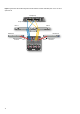
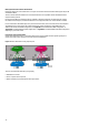
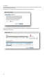
Figure 7: Typical Fabric-Attach SAN configuration with VC FlexFabric modules. Redundant paths - Server-to- Fabric
uplink ratio 4:1
Enclosure
UID
Enclosure Interlink
PS
3
PS
2
PS
1
PS
6
PS
5
PS
4
OA1 OA2
Remove management modules before ejecting sleeve
FAN
6
FAN
10
FAN
1
FAN
5
2
1
3
5
7
4
6
8
iLO
UID
Active
Reset
iLO
UID
Active
Reset
HP V C Fl exF ab ri c 1 0G b/2 4- Po rt Mo du le
SHAR E D: U P LI NK or X- LI N K
X3 X4X1 X2 X5 X6 X7 X8
UID
HP V C Fl exF ab ri c 1 0G b/2 4- Po rt Mo du le
SHAR E D: U P LI NK or X- LI N K
X3 X4X1 X2 X5 X6 X7 X8
UID
Console Unit
5 6 15 1613 1411 129 107 81 2 3 4 21 22 31 3229 3027 2825 2623 2417 18 19 20 37 38 47 4845 4643 4441 4239 4033 34 35 36
Series
100%
80%
60%
40%
20%
49 525150
RPS
PWR
10/100Base-TX 1000Base-X
H3C S 36 00
Speed:Green=100Mbps,Yellow=10Mbps
Duplex:Green=Full Duplex,Yellow=Half Duplex Power:Green=DeliveringPower,Yellow=Fault,Flashing Green=Over Budget
Green=Speed
Mode
Yellow=Duplex
Flashing=PoE
DP1-A DP1-B1 2 DP1-A DP1-B1 2
Cntrl 2
Mgmt
UID
Cntrl 1
PS 2PS 1
UID UID
Mfg Mfg
12Vdc 12 Vdc
HP StorageWorks
4/32B SAN Switch
0 1 2 3 8 9 10 11 16 17 18 19 24 25 26 27 3130292823222120151413127654
12Vdc 12 Vdc
HP StorageWorks
4/32B SAN Switch
0 1 2 3 8 9 10 11 16 17 18 19 24 25 26 27 3130292823222120151413127654
Fabric-1
Fabric-2
Storage Array
LAN Switch A
LAN Switch B
SUS-1
SUS-2
SAN uplink
connection
Ethernet uplink
connection
Storage Controller Storage Controller
SAN Switch A SAN Switch B
Console Unit
5 6 15 1613 1411 129 107 81 2 3 4 21 22 31 3229 3027 2825 2623 2417 18 19 20 37 38 47 4845 4643 4441 4239 4033 34 35 36
Series
100%
80%
60%
40%
20%
49 525150
RPS
PWR
10/100Base-TX 1000Base-X
H3C S 36 00
Speed:Green=100Mbps,Yellow=10Mbps
Duplex:Green=Full Duplex,Yellow=Half Duplex Power:Green=DeliveringPower,Yellow=Fault,Flashing Green=Over Budget
Green=Speed
Mode
Yellow=Duplex
Flashing=PoE
Ethernet uplink
connection
HP BladeSystem c7000