
HP Virtual Connect for c-Class BladeSystem Setup and Installation Guide


Component identification 117
Resetting the Administrator password and DNS
settings
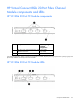
To return the VC-Enet module to factory default settings for the Administrator password and DNS settings, you
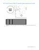
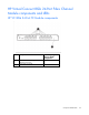
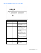
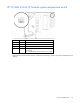
must access the system maintenance switch. For switch locations, see the appropriate module system
maintenance switch information.
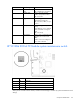
When the VC-Enet module system maintenance switch 1 is in the ON position, the following actions occur:
• The firmware restores the Administrator account password and DNS Settings to the factory defaults
listed on the module label (without disturbing any other local user accounts).
• The VC-Enet module management console displays the Administrator account password. To access the
console, see the HP BladeSystem Onboard Administrator User Guide
(http://h20000.www2.hp.com/bc/docs/support/SupportManual/c00705292/c00705292.pdf
).
While switch 1 is in the ON position and reserved switches are in the OFF position, passwords are restored
during each power-up sequence, but changes are not allowed.
After switch 1 is returned to the OFF position, the following conditions exist:
• Users with appropriate privileges can change the Administrator password.
• The VC-Enet module management console no longer displays the Administrator password.
To recover a password:
1. Remove the Virtual Connect Ethernet module from interconnect bay 1.
2. Remove the access panel from the Virtual Connect Ethernet module.
3. Set switch 1 to the ON position. Be sure that all other switches remain in the OFF position.
4. Install the access panel.
5. Install the Virtual Connect Ethernet module into bay 1 and allow the module to power up and reach a
fully booted and operational state (approximately 1 minute).
6. Remove the Virtual Connect Ethernet module from interconnect bay 2.
This action forces the module in interconnect bay 1 to run the active VC Manager. Because switch 1 is
set, the Administrator password remains at the factory default for interconnect bay 1 (not overwritten by
the change of state because of the failover).
7. Wait to ensure that the VC Manager has had time to become active on the module in interconnect bay
1. Log in to the VC Manager to confirm it is active.
8. Insert the Virtual Connect Ethernet module into interconnect bay 2 and allow the module to power on
and reach a fully booted and operational state (approximately 1 minute).
9. Remove the Virtual Connect Ethernet module from interconnect bay 1.
10. Remove the access panel from the Virtual Connect Ethernet module.
11. Set switch 1 to the OFF position. Ensure that all other switches remain in the OFF position.
12. Install the access panel.
13. Install the Virtual Connect Ethernet module into interconnect bay 1 and allow the module to power up
and reach a fully booted and operation state (approximately 1 minute).
14. Log in to the active VC Manager. Use the factory default user name and password to log in to the
module, regardless of its location in interconnect bay 1 or interconnect bay 2.