
HP Virtual Connect for c-Class BladeSystem Setup and Installation Guide
Installation 25
• It monitors and intercepts common loop detection frames used in other switches. In network
environments where the upstream switches send loop detection frames, the VC Enet modules must
ensure that any downlink loops do not cause these frames to be sent back to the uplink ports. Even
though VC probe frames ensure loops are detected, there is a small time window depending on the
probe frame transmission interval in which the loop detection frames from the external switch might loop
through down link ports and reach uplink ports. By intercepting the external loop detection frames on
downlinks, the possibility of triggering loop protection on the upstream switch is eliminated. When
network loop protection is enabled, VC-Enet modules intercept the following types of loop detection
frames:
o PVST+ BPDUs
o Procurve Loop Protect frames
When the network loop protection feature is enabled, any probe frame or other supported loop detection
frame received on a downlink port is considered to be causing the network loop, and the port is disabled
immediately until an administrative action is taken. The administrative action involves resolving the loop
condition and clearing the loop protection error condition. The "loop detected" status on a port can be
cleared by one of the following administrative actions:
• Restart loop detection by issuing "reset" loop protection from the CLI or GUI
• Unassign all networks from the port in "loop detected" state
The SNMP agent supports trap generation when a loop condition is detected or cleared.
Virtual Connect provides the ability to enable or disable network loop protection. The feature is enabled by
default and applies to all VC-Enet modules in the domain. Network loops are detected and server ports can
be disabled even prior to any enclosure being imported.
A loop-protect reset command resets and restarts loop detection for all server ports in a “loop-detected” error
condition.
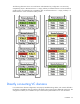
For each individual network in the Virtual Connect environment, VC blocks certain stacking links to ensure
that each network has a loop-free topology. VCM determines which stacking links are used to forward traffic
by determining the shortest route from the module with the active uplink to the remaining stacked VC-Enet
modules. For optimal stacking strategies, see HP Virtual Connect for the Cisco Network Administrator on the
Functionality & Value tab of the HP BladeSystem Technical Resources website
(http://www.hp.com/go/bladesystem/documentation).
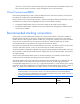
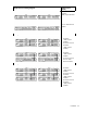
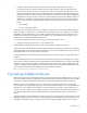
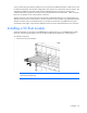
Connecting multiple enclosures
Virtual Connect version 2.10 and higher supports the connection of up to four c7000 enclosures, which can
reduce the number of network connections per rack and also enables a single VC manager to control multiple
enclosures. A single set of cables can be used to carry all external Ethernet traffic from a single rack.
Multiple enclosure support enables up to four c7000 enclosures to be managed within a single Virtual
Connect domain. This configuration supports up to 16 VC-Enet modules and up to 16 VC-FC modules in the
same domain, with a maximum of 4 VC-Enet, or 4 VC-FC modules per enclosure. Using multiple c7000
enclosures, you can install up to 16 FlexFabric modules in the same domain. Each FlexFabric Module counts
as 1 VC-Enet module and 1 VC-FC module towards the 16 maximum module limit per multi-enclosure
domain.
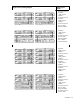
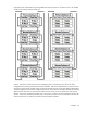
Stacking multiple enclosures enables the management of up to four enclosures from a single control point. VC
Manager operates in the primary enclosure, and it enables up to three additional remote enclosures of the
same type to be added as part of a single VC domain. The locally managed primary enclosure must be