
HP Virtual Connect for c-Class BladeSystem Setup and Installation Guide

Installation 39
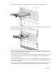
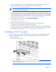
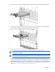
Connecting Virtual Connect Ethernet module uplinks
Each interconnect module has several numbered Ethernet connectors. All of these connectors can be used to
connect to data center switches (uplink ports), or they can be used to stack Virtual Connect modules as part
of a single Virtual Connect domain (stacking ports). See "Recommended stacking connections (on page
21)."
Networks must be defined within VCM so that specific named networks can be associated with specific
external data center connections. These named networks can then be used to specify networking connectivity
for individual servers. The network connection can be between one or many networks to one or many uplink
ports:
• One network to one port (unshared network)
• One network to multiple uplink ports (unshared network)
• Multiple networks to one port (shared uplink set)
• Multiple networks to multiple ports (shared uplink set)
In addition, multiple networks can be connected to server downlink ports using server VLAN IDs. For more
information, see "Managing server profiles" in the user guide.
The following sections provide an overview of the types of external connections and their behaviors.
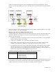
Mapping individual networks to individual external uplink ports
The simplest approach to connecting the defined networks to the data center is to map each network to a
specific external uplink port. This uplink port is defined by the following:
• Enclosure name
• Interconnect bay containing the VC-Enet module
• Selected port on that module
Port status indicators can be used to locate a specific port or to provide additional status.
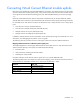
The following table shows an example of simple network mapping, where the Virtual Connect enclosure is
named Enclosure1 and VC-Enet modules are in interconnect module bays 1 and 2.
Network Uplink port
Production_Network
Enclosure1:Bay1:PortX2
Dev_Network
Enclosure1:Bay1:Port4
Backup_Network
Enclosure1:Bay2:Port3
iSCSI_Storage_Network
Enclosure1:Bay2:PortX2