
HP Virtual Connect for c-Class BladeSystem Setup and Installation Guide

Installation 42
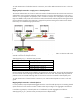
Network Shared uplink set and VLAN
Production_Network
Shared_Uplink_Set_A:VLAN_15
Dev_Network
Shared_Uplink_Set_A:VLAN_21
Backup_Network
Shared_Uplink_Set_A:VLAN_32
iSCSI_Storage_Network
Shared_Uplink_Set_A:VLAN_76
In this example, all of the defined networks share a single active uplink port (such as
Enclosure1:Bay1:PortX2) using VLAN tagging, while the second link in the shared uplink set is available for
failover. The shared uplink set can also be constructed from multiple 1-Gb external ports.
To make VCM aware of shared network connections, see "Define Shared Uplink Set screen" in the user
guide.
Configuration example using a Cisco Core switch
There are several ways to implement a redundant Virtual Connect configuration. This example provides a
reference for anyone unfamiliar with switch configurations. This example is just one of several ways to
connect an HP Virtual Connect to a Cisco Core switch. For more information, see HP Virtual Connect for the
Cisco Network Administrator on the Functionality & Value tab of the HP BladeSystem Technical Resources
website (http://www.hp.com/go/bladesystem/documentation).
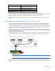
Connecting Virtual Connect to a Cisco Core/distribution switch using a shared uplink set and VLAN tagging
done at the VC/data center boundary
In the following example, LACP is used on the Cisco Switch to connect to a shared uplink set using three
uplink ports. VLANs 10, 20, 30, and 40 from the network are tagged on the three shared uplink ports.
IMPORTANT: Change Channel Mode to LACP on the Cisco switch.
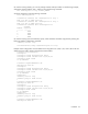
By default, all ports on a Catalyst 4500/4000 switch and a Catalyst 6500/6000 switch use channel
protocol PAgP and are not running LACP. For all ports concerned, you must change the channel mode to
LACP.