
HP Virtual Connect for c-Class BladeSystem Setup and Installation Guide
HP Virtual Connect Manager 92
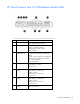
Verify link and speed
To verify that all external ports connected to the data center are linked and are operating at the appropriate
speed:
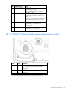
1. Verify that all VC-Enet and FlexFabric modules are powered on and functioning properly. The module
status LED should be green for all modules connected and configured in Virtual Connect for data center
use.
If the LED is not green, use the HP Onboard Administrator user interface to diagnose the problem and
verify that the module is powered on.
2. Verify that all VC-FC modules are powered on and functioning properly. The module status LED should
be green for all modules connected and configured in Virtual Connect for data center use.
If the LED is not green, use the HP Onboard Administrator user interface to diagnose the problem and
verify that the module is powered on.
3. Verify that the data center switches are powered on.
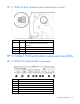
4. Verify that each external port is linked and operating at the appropriate speed using link/speed activity
LEDs for that port.
If ports are not linked, verify that the cables being used are not defective, and verify that both ends of
the link are configured for the same speed/duplex settings. Both sides of the configuration must match
for the link to be established. For autonegotiation, both ports must be configured to run autonegotiation.
To use a forced speed, (for example, 100 Mb full-duplex), both ports must be configured to be the same
forced speed. Mismatched configuration can result in ports not linking up or not functioning properly.
VC-Enet and FlexFabric modules do not support half-duplex operations.
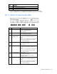
5. Verify that the port status indicator (port number) of each configured external port is illuminated green,
assuming no port IDs are enabled. This status indicates that the port is actively configured as part of an
external connection.
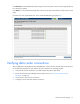
Verify network status using VC Manager
VCM provides many status and summary screens that can be used to verify that the networks were defined
properly and mapped to the appropriate network.
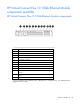
One useful summary screen is the Ethernet Networks (Summary) screen. To access this screen, click the
Ethernet Networks link in the left navigation tree.
The following actions are available from this screen:
• Identify the external ports associated with each Ethernet network.
• View the current port status (link, speed) of each external port.
• View the current active/standby state of each external port.
• Access information about attached switches (if the external switch supports LLDP).
• Highlight the port IDs for all external ports associated with a specific network.