
HP Virtual Connect for c-Class BladeSystem Setup and Installation Guide

Component identification 96
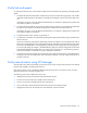
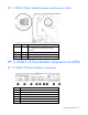
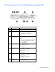
Item Description
7
Next button
8
Ports 1-4 (10/100/1000BASE-T)
9
Reset button (recessed)
* Supports 10GBASE-SR-XFP and 10GBASE-LR-XFP pluggable optical transceiver modules
** Supports 1000BASE-T-SFP and 1000BASE-SX-SFP pluggable optical transceiver modules
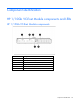
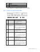
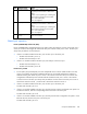
HP 1/10Gb-F VC-Enet Module LEDs
Item LED description Status
1
Module status Green = Normal operation
Amber = Degraded condition
Off = Power off
2
Module locator (UID) Blue = Module ID selected
Off = Module ID not selected
3
X1 port status
(10GBASE-CX4)
Green = Port is configured and operating as
an uplink port connected to a data center
fabric.
Amber = Port is operating as a stacking link
interconnecting Virtual Connect modules.
Blue = Port locator (PID)
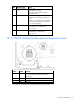
4
X1 link/port activity Green = Link
Green flashing = Activity
Off = No link
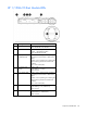
5
Port X2/X3 status Green = Port is configured and operating as
an uplink port connected to a data center
fabric.
Amber = Port is operating as a stacking link
interconnecting Virtual Connect module.
Blue = Port locator (PID)
6
Port X2/X3 activity Green = Link
Green flashing = Activity
Off = No link, unsupported or absent
pluggable module
7
Port S1/S2 status Green = Port is configured and operating as
an uplink port connected to a data center
fabric.
Amber = Port is operating as a stacking link
interconnecting Virtual Connect module.
Blue = Port locator (PID)