
HP Virtual Connect for c-Class BladeSystem Version 2.30 User Guide

Server management 112
the environment.
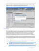
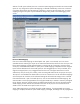
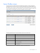
Defining a Server Profile
If VC-assigned MAC addresses, WWNs, or non-default Fibre Channel boot parameters are being used,
always power off the affected server blades before assigning a profile. When assigning a VC-assigned
serial number (logical), power off the server. To power off a server blade, see "Server Bay status screen
(on page 160)."
To define a server profile:
1. Enter the server profile name.
The server profile name can be up to 64 characters in length (no spaces). Because the server profile
can be assigned to different locations, HP recommends that the name reflect the server function. The
profile can be renamed at any time.
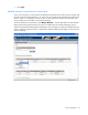
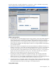
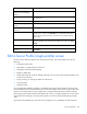
2. Set up Ethernet Network Connections for ports 1 and 2. For each port, do the following:
a. To select an available Ethernet network, click the down arrow under Network Name.
b. To override the current PXE settings on the server, click the down arrow under PXE and select
Disabled or Enabled.
Only one port can have PXE enabled by Virtual Connect on a server blade. However, if the
default 'Use BIOS' setting is selected, the server uses the current settings in the BIOS. On
mezzanine cards only, the 'Use BIOS' selection can allow more than one NIC port to have PXE
enabled. Only one embedded NIC can have PXE enabled.
The MAC field indicates whether the profile uses a server factory default or a VC-defined MAC
address. VC-defined MAC addresses are not assigned until the profile is created.
PXE allows an Ethernet port to be used for a network boot. PXE should only be enabled on a port
that is connected to a network with a properly configured PXE environment.
3. If the server will use more than two network connections, click Add Network Connection, and then
select the appropriate network.
When additional network connections are added, the X in the Delete column becomes active for
those new connections. Click the X to delete additional network connections from the list.
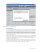
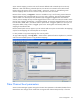
4. If the VC domain contains VC-FC modules, set up the Fibre Channel connections. Two Fibre Channel
connections exist for each set of horizontally adjacent interconnect bays in the enclosure that contain
VC-FC modules. For each port, do the following:
a. Click the down arrow under FC SAN connection to select an available SAN.
b. Click the down arrow under Port Speed to select Auto, 2Gb, 4Gb, 8Gb, or Disabled for that port.
Auto is the default.
5. To modify the Fibre Channel boot parameters, select the Show Fibre Channel Boot Parameters
checkbox. See "Fibre Channel boot parameters (on page 117)."
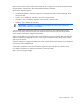
6. To assign the server profile to a device bay, click the down arrow next to Select Location to select an
enclosure and bay number. This step can be deferred.
If a server blade is present in the selected location, it must be powered off for the profile to be saved
and assigned properly.
For more information on server power requirements when assigning or removing server profiles, see
"Server profile troubleshooting (on page 124)."