
HP Virtual Connect for c-Class BladeSystem Version 3.00 Setup and Installation Guide for HP Integrity BL8x0c i2 Series Server Blades


Installation 62
switchport
switchport trunk encapsulation dot1q
switchport trunk allowed vlan 10,20,30,40
switchport mode trunk
no ip address
interface GigabitEthernet7/46
description test-VC
switchport
switchport trunk encapsulation dot1q
switchport trunk allowed vlan 10,20,30,40
switchport mode trunk
no ip address
speed 1000
channel-protocol lacp
channel-group 10 mode active
!
interface GigabitEthernet7/47
description test-VC
switchport
switchport trunk encapsulation dot1q
switchport trunk allowed vlan 10,20,30,40
switchport mode trunk
no ip address
speed 1000
channel-protocol lacp
channel-group 10 mode active
!
interface GigabitEthernet7/48
description test-VC
switchport
switchport trunk encapsulation dot1q
switchport trunk allowed vlan 10,20,30,40
switchport mode trunk
no ip address
speed 1000
channel-protocol lacp
channel-group 10 mode active
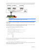
Failover and check-pointing
Virtual Connect Manager runs as a high-availability pair when Virtual Connect Ethernet modules are
installed in horizontally adjacent interconnect bays. The active VC Manager is usually on the lowest odd
numbered bay when the enclosure is powered up.
IMPORTANT: To support high availability, always install Virtual Connect Ethernet modules in
horizontally adjacent interconnect bays.
If you are not using dynamic DNS, use the Onboard Administrator to access the Virtual Connect Ethernet
module in the primary bay. Then, you can optionally set a Virtual Connect Domain IP address so that you
have a consistent IP address to access VC Manager, whether it is running from the primary bay or the
secondary bay because of a failover.
Each time a configuration is changed, it is written to local flash memory and then check-pointed to the
standby module. Configurations can also be backed up to a workstation using the GUI or Virtual Connect
Support Utility.