
HP Virtual Connect for c-Class BladeSystem Version 3.00 User Guide for Integrity BL8x0c i2 Server Blades

Network management 56
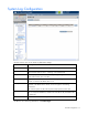
3.
Select whether to designate (checked) or not designate (unchecked) this network as a private
network ("Private Networks" on page 53).
4. Select whether to enable (checked) or disable (unchecked) VLAN tunneling ("Server VLAN Tagging
Support" on page 69).
This option is only available if the 'Tunnel VLAN Tags' radio button was previously selected on the
Advanced Settings tab of the Ethernet Settings screen.
5. If the network is to be used only internal to the Virtual Connect domain or enclosure, go to step 7 (do
not add any external ports).
6. Use the Add Port pull-down menu to add one or more external ports. To ensure a high availability
connection, select two or more ports.
Only available ports are listed, displaying the current port link status.
To create an internal network, which connects one server to another, do not select a port. Enter the
network name, and then click Define Network.
7. Select the Connection Mode:
o Auto (recommended)—This mode enables the uplinks to attempt to form aggregation groups
using IEEE 802.3ad link aggregation control protocol, and to select the highest performing uplink
as the active path to external networks.
Aggregation groups require multiple ports from a single Virtual Connect Ethernet module to be
connected to a single external switch that supports automatic formation of LACP aggregation
groups. Multiple aggregation groups may be formed from the ports selected for the network. The
highest performing aggregation group is selected as active, with other aggregation groups and
individual links used as standby connections.
o Failover—If this mode is selected, set the port to Primary or Secondary. Only a single link is used
as the active link to the external networks, with other ports used as standby connections.
8. Click Apply. The network is now defined and available for use in creating server profiles.
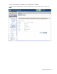
To define a network that uses an existing Shared Uplink Set, either use the Define/Edit Shared Uplink Set
screen, or define the additional network as follows:
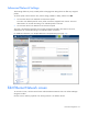
1. Enter the network name.
2. Select the Use Shared Uplink Set box.
3. Select an existing Network from the dropdown list or click the Create icon.
If the Create icon is selected, the Define a Shared Uplink Set screen appears so that a new Shared
Uplink Set can be created.
4. Enter an external VLAN ID.
5. Click Apply.
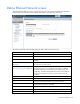
IMPORTANT: For best performance, HP recommends limiting the number of VLANs on one
shared uplink set to 128 and limiting the number of shared uplinks sets in one domain to two.
NOTE: By default, Virtual Connect supports Jumbo Frames up to 9KB.