
HP Virtual Connect for c-Class BladeSystem Version 3.00 User Guide for Integrity BL8x0c i2 Server Blades

Network management 60
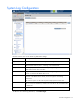
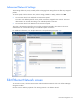
This summary screen displays the external connections for each network and is available to all authorized
users.
The following table describes the columns within the summary table on the Ethernet Networks (Summary)
screen.
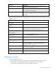
Column name Description
Ethernet Networks Shows the overall network status and network name
PID Shows the PID state of the network
Shared Uplink Set (VLAN ID)
Shows the name of the shared uplink set and its VLAN ID (if
applicable)
Port Status
Shows whether each individual port associated with the network is
linked or unlinked and the current link speed
Connector Type Displays the type of connector on the port; for example, RJ-45
Connected to
If the individual port is connected to a switch that supports LLDP, the
switch MAC address and switch port appear. A link is provided to
obtain more information about the far-end switch port.
Uplink Port
Lists the status of the individual port and the location of the individual
port (enclosure, bay, port)
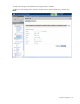
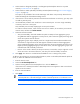
The following table describes the available actions in the Ethernet Networks (Summary) screen. Clicking
another link in the pull-down menu or left navigation window causes current edits that have not been
applied to be lost.
Task Action
Sort list view
Click the down arrow next to the Show box to display All Networks, or
one specific network.
Edit a network
Left-click on the network row, right-click to display a menu, and then
select Edit.
Edit a shared uplink set
Left-click on the shared uplink set row, right-click to display a menu,
and then select Edit.