
HP Virtual Connect for c-Class BladeSystem Version 3.00 User Guide for Integrity BL8x0c i2 Server Blades

Network management 77
1.
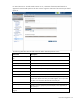
Enter the shared uplink set name. The uplink set name can be up to 64 characters in length (no
spaces).
2. Add one or more external ports using the Add Port pull-down menu. Only available ports are listed,
and they display the current port link status. Select two or more ports to ensure a high availability
connection.
3. Select the speed and duplex (where applicable) of the uplink ports. Click the drop-down box under
Speed/Duplex, and then select a setting. Half-duplex operation is not supported by the Virtual
Connect Ethernet module.
IMPORTANT: Be sure that the uplink interface port speed matches the speed set on the
corresponding network switch port. If using autonegotiation, both ports must be configured to
use autonegotiation or they might not link.
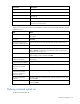
4. Select the Connection Mode:
o Auto (recommended)—This mode enables the uplinks to attempt to form aggregation groups
using IEEE 802.3ad link aggregation control protocol, and to select the highest performing uplink
as the active path to external networks.
Aggregation groups require multiple ports from a single Virtual Connect Ethernet module to be
connected to a single external switch that supports automatic formation of LACP aggregation
groups. Multiple aggregation groups may be formed from the ports selected for the network. The
highest performing aggregation group is selected as active, with other aggregation groups and
individual links used as standby connections.
o Failover—If this mode is selected, set the port to Primary or Secondary. Only a single link is used
as the active link to the external networks with other ports used as standby connections.
5. Identify the Associated Networks that will use this shared uplink:
a. Right-click the header row in the Associated Networks table to display a menu, and then select
Add.
b. Enter the name of the network.
c. Enter the number for the VLAN ID (1 to 4094) for that network as defined by the network
administrator and as configured on the external Ethernet switch.
d. Select whether to enable (checked) or disable (unchecked) native VLAN. Only one network can
be selected as the native VLAN. See "Shared uplink sets and VLAN tagging (on page 74)."
e. Select whether to enable (checked) or disable (unchecked) Smart Link (on page 53).
f. Select whether to designate (checked) or not designate (unchecked) the network as a private
network ("Private Networks" on page 53).
g. Repeat steps a through f for all networks to use the shared uplink set.
6. Click Apply. The shared uplink and associated networks are now defined and available for use in
creating server profiles.
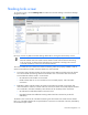
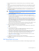
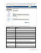
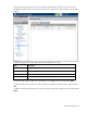
Edit Shared Uplink Set screen
To access this screen, click the shared uplink set to be edited in the left VC Manager navigation window.