
HP Virtual Connect for c-Class BladeSystem Version 3.30 User Guide

Virtual Connect server profiles 118
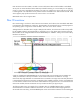
and SAN boot settings and connects the appropriate networks and fabrics. Server blades that have been
assigned a profile and remain in the same device bay do not require further Virtual Connect Manager
configuration during a server or enclosure power cycle. They boot and gain access to the network and fabric
when the server and interconnect modules are ready.
If a server blade is installed in a device bay already assigned a server profile, Virtual Connect Manager
automatically updates the configuration of that server blade before it can power on and connect to the
network.
If a server blade is moved from a Virtual Connect-managed enclosure to a non-Virtual Connect enclosure,
local MAC addresses and WWNs are automatically returned to the original factory defaults. This feature
prevents duplicate MAC addresses and WWNs from appearing in the data center because of a server blade
redeployment.
Multi-blade servers
Certain HP Integrity server blades can be conjoined using a Scalable BladeLink (SBL) to create a single
server. These servers are treated just like other server blades even though they are comprised of several
physical server blades.
IMPORTANT: The term server blade, when applied to a multi-blade server, means the entire
conjoined server, and not just a single server blade. For example, "a server profile is assigned to
a server blade" means that a single server profile is assigned to an entire multi-blade server.
In each multi-blade server one blade is identified as the monarch blade. The other blades are referred to as
auxiliary blades. In most multi-blade servers the lowest numbered bay in the server is the monarch, but that
is not always the case. Both the VCM CLI and GUI identify the monarch in the information provided for a
multi-blade server. All communication to a multi-blade server, such as to the iLO user interface, is done
through the monarch blade.
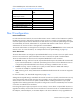
VCM displays multi-blade servers as a single entity showing the range of bays that comprise the server. For
example, if a multi-blade server occupies bays 1, 2, 3, and 4, then VCM represents the server as “Bays 1-4
(HP Integrity BL890c i2)”. This is true in the Server Bays summary screen, in the list of bays that a profile can
be assigned to in the Edit Server Profile screen, and so on.
A profile is assigned to an entire multi-blade server, not to the individual blades in the server. If a profile is
assigned to an auxiliary blade (for example, a profile is assigned to an empty bay and then a multi-blade
server is installed) that profile is ignored (in this case it’s the same as a profile assigned to a covered bay).
In such a case VCM identifies the bay that the profile is assigned to as “Covered – Auxiliary”.
VCM maps the profile connection entries to ports on the blades in a multi-blade server as follows:
• Ethernet profile connection entries are evenly distributed across all of the blades in a multi-blade server.
For example, if a multi-blade server is comprised of 4 blades then the 1st, 5th, 9th, etc Ethernet
connections are assigned to the first blade, the 2nd, 6th, 10th etc Ethernet connections are assigned to
the second blade, and so forth. Connection entries to specific ports on a blade are mapped the same
way as for other full-height blades.
For more information, see "Port assignment."
• FC profile connection entries are mapped to blades such that all of the FC HBAs on the first blade are
mapped first, then the HBAs on the second blade, and so on. When a profile is first created it will have
enough FC profile connections for the HBAs on one blade. More FC connections can be added only
after the profile has been assigned to a multi-blade server. The maximum number of FC connections
allowed is N times the original number of entries, where N is the number of blades in the multi-blade
server that a profile is assigned to.