
HP Virtual Connect for c-Class BladeSystem Version 3.30 User Guide

Virtual Connect networks 86
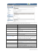
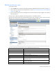
Field name Description
information about possible causes, see "Port status conditions (on page
203)."
Connector Type
Displays the type of connector on the port; for example, RJ-45
Connected to
If the port is connected to a switch that supports LLDP, the switch MAC
address and switch port appear. A link is provided to obtain more
information about the far-end switch port.
PID
When selected, sets/clears the port identifier color as blue on the VC-Enet
module to aid in the location of the specific uplink. The PID status for the
overall network also appears.
Speed/Duplex
Pull-down menu to specify the speed and duplex (where applicable) of the
uplink port. Half-duplex operations are not supported by the VC-Enet
module.
Network Access Groups
Displays the Network Access Groups that include this network.
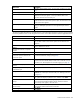
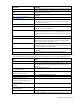
The following table describes the available actions in the Define Ethernet Network Screen. Clicking another
link in the pull-down menu or left navigation tree causes current edits that have not been applied to be lost.
Task Action
Define network color
Select a color from the Color pull-down menu.
Define network label
Type a label in the Labels field, and then press Enter
. A network can have
up to 16 labels. Labels cannot contain spaces and are limited to 24
characters.
Enable Smart Link on the network being
defined
Select the Smart Link checkbox. The checkbox is not available until an
uplink is added to the network.
Designate the network as a private
network
Select the Private Network checkbox.
Enable VLAN tunneling
Select the Enable VLAN Tunneling checkbox.
Set a custom value for preferred link
connection speed or maximum link
connection speed
Select the Advanced Network Settings checkbox. For more information,
see "Advanced Network Settings (on page 88)."
Enable the selection of a shared uplink
set
Select the Use Shared Uplink
set checkbox, select the shared uplink set to
which this network should be added, and then enter a VLAN ID. For more
information, see “Shared uplink sets and VLAN tagging (on page 70)."
Add an external uplink port to the
network
Use the cascading menu to select a port, and then click Add.
Change the uplink interface port speed
or disable the port
Click the pull-down box under Speed/Duplex, and then select a setting.
Change the connection mode
Click the pull-down box next to Connection Mode, and then select Auto
or Failover. For a description of these modes, see "Defining a network
(on page 87)."
Delete an added port
Click the Delete link in the Action column, or left-click to select the line
item, right-click to display a pull-down menu, and then select Delete.
Add this network to Network Access
Groups
In the Network Access Groups field, begin typing the name of a Network
Access Group that should include this network. When the Network
Access Group name appears, select the name.
Remove this network from Network
Access Groups
In the Network Access Groups field, click the X next to the Network
Access Group name that should not be included.
Save changes
Click Apply.
Cancel without saving changes
Click Cancel.